I have a peltier (12 V and 7 Amps) and I want to control its temperature using Arduino. I was using the N channel dual MOSFET module and it worked just fine except that it does not switch polarities.
I have read about H bridges but still not sure and it is better to ask about that any professional or experienced engineer. Are there any modules to directly use with my application or should I build it myself?
A big relay, such as used in cars, will work. For example a 12V 20A relay. They cost a few dollars/euros. You still need that mosfet module to power the relay. A relay that can be a H-bridge is called a DPDT relay (Double Pole, Double Throw).
Can you give a link to your mosfet module ?
I prefer mosfets instead of relays. There are motor drivers for that current. For example this one: https://www.pololu.com/product/1363.
It costs 119 dollars. Let's see what others come up with, to get that price down.
Thank you!
This is the module I'm using: High-Power Dual MOSFET Switch Module - ProtoSupplies
So if I use the motor driver you showed, then alone will be enough for the controlling and no need for the relay and the MOSFET module. And as you said, it's so expensive..
That is Four Pin Double Throw (4PDT), but the contacts will melt with 7A.
A good brand has good specifications. If you go to you local car-spare-part-shop, then they have a good relay.
A relay from Ebay/AliExpress/Amazon that is 20A can perhaps switch only 1A.
You can also use two relays with a single switching pole. For a H-bridge, they don't have to switch at the same time. But you do need another mosfet module to drive the other relay.
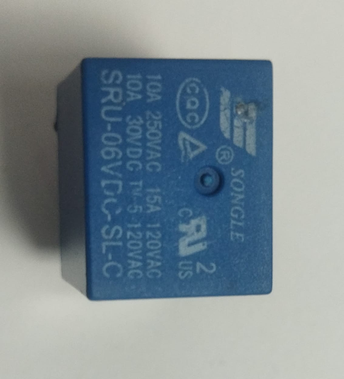
I found this in my electronics box, I guess it's DPDT and can handle our application, but it states a 30VDC and the power supply is 12V, will this affect its function?
Edit: It's 6V not 30 as in its name. But what's the difference between the 6 and 30 written?
Edit2: I think it's not a DPDT..
It is an SPDT
Oops, silly me, you can use the your mosfet module to turn on two SPDT relays of course. Sorry. You don't have to buy an other mosfet module.
The SPDT car relays are easier to get, you need two of those.
If you want to have some fun with the relays, then you can open a car relay and open that blue relay. The car relay has big sturdy contacts and the blue relay has flimsy metals.
THANKS.
So maybe my connections would be like the image above but instead of the Motor, I have a Peltier. The thing is that I want the Arduino, depending on the temperature read, do the switching of the poles.
In the image above, there is only one power supply which is 12V that is running everything, in my case I will be having a 12V power supply plus the Arduino in order to send signals to turn the relays on and off in order to heat and cool. And what's the role of the dual MOSFET module in this case? You have stated to deliver power to the relay, but how would the connections be. I'm a bit confused, can you please draw a simple circuit of what could it be?
The blue relay might work for 5 minutes or half a year, but relay contacts sticking together is hard to detect because it may still make a "click" sound. You will be wasting a lot time to figure that out when it happens.
An Arduino pin has not enough current for the relay coil and if you have 12V for the peltier then it is easier to use a 12V relay (a relay with a 12V coil).
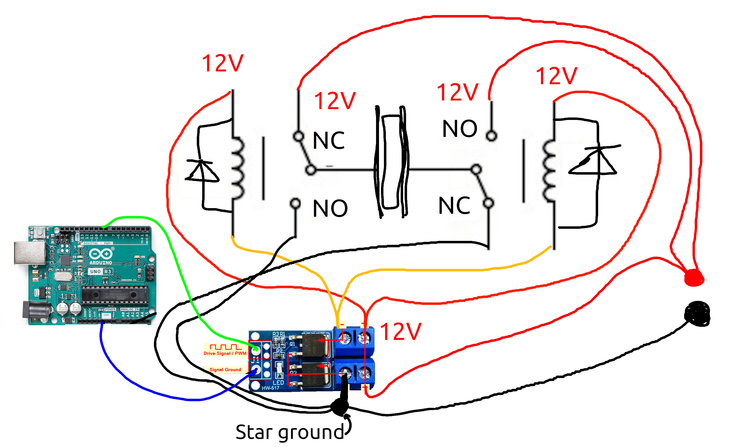
We always say on this forum to make a nice schematic and not a bad spaghetti picture Well, here is a bad spaghetti picture:
I tried to show the star ground. The GND from the Arduino meets the GND from the 12V in the mosfet module. The thick GND wire from the mosfet module to the star ground should be short.
The green wire is the signal from the Arduino board and the orange wires are to the relays. The rest is just GND and 12V.
Do you also want to be able to turn the peltier off ?
You can apply 12V or GND to both sides of the peltier to turn it off, but then you need two mosfet modules, or a darlington transistor or something else that can drive a relay.
You will instantly destroy a Peltier device if you switch polarity WITHOUT waiting for the internal heat to dissipate. likely to be 15 minutes with good heat sinks. Been there and done that.