Hi,
We're trying to read a rotary encoder. I've got a document with 27 pages of thing (code) we've already tried, but it gave either nothing or random things as output.
I don't know what is usually done when troubleshooting these kind of things, so ask me any information you want about the project.
First.
The encoder we use.
24 pulses / 360° for each phase
incremental encoder (not absolute)
quadrature
Second.
The code we tried:
Example 1.
/* read a rotary encoder with interrupts
   Encoder hooked up with common to GROUND,
   encoder0PinA to pin 2, encoder0PinB to pin 4 (or pin 3 see below)
   it doesn't matter which encoder pin you use for A or B

   uses Arduino pullups on A & B channel outputs
   turning on the pullups saves having to hook up resistors
   to the A & B channel outputs

*/

#define encoder0PinA  2
#define encoder0PinB  3

volatile unsigned int encoder0Pos = 0;

void setup() {


  pinMode(encoder0PinA, INPUT);
  digitalWrite(encoder0PinA, HIGH);       // turn on pullup resistor
  pinMode(encoder0PinB, INPUT);
  digitalWrite(encoder0PinB, HIGH);       // turn on pullup resistor

  attachInterrupt(0, doEncoder, CHANGE);  // encoder pin on interrupt 0 - pin 2
  Serial.begin (9600);
  Serial.println("start");                // a personal quirk

}

void loop(){
// do some stuff here - the joy of interrupts is that they take care of themselves
}

void doEncoder() {
  /* If pinA and pinB are both high or both low, it is spinning
   * forward. If they're different, it's going backward.
   *
   * For more information on speeding up this process, see
   * [Reference/PortManipulation], specifically the PIND register.
   */
  if (digitalRead(encoder0PinA) == digitalRead(encoder0PinB)) {
    encoder0Pos++;
  } else {
    encoder0Pos--;
  }

  Serial.println (encoder0Pos, DEC);
}

/*  to read the other two transitions - just use another attachInterrupt()
in the setup and duplicate the doEncoder function into say,
doEncoderA and doEncoderB.
You also need to move the other encoder wire over to pin 3 (interrupt 1).
*/
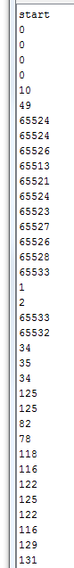
That didn't work. The serial monitor did start, but when I turned the encoder nothing happened. Pins of the encoder are on 2,3 and gnd.
Then we edited it according to the last paragraph.
#define encoder0PinA  2
#define encoder0PinB  3

volatile unsigned int encoder0Pos = 0;

void setup() {


  pinMode(encoder0PinA, INPUT);
  digitalWrite(encoder0PinA, HIGH);       // turn on pullup resistor
  pinMode(encoder0PinB, INPUT);
  digitalWrite(encoder0PinB, HIGH);       // turn on pullup resistor

  attachInterrupt(0, doEncoderA, CHANGE); // encoder pin on interrupt 0 - pin 2
attachInterrupt(1, doEncoderB, CHANGE);  // encoder pin on interrupt 1 - pin 3
    Serial.begin (115200);
  Serial.println("start");                // a personal quirk
  Serial.println (encoder0Pos, DEC);

}

void loop(){

}


void doEncoderA() {
  /* If pinA and pinB are both high or both low, it is spinning
   * forward. If they're different, it's going backward.
   *
   * For more information on speeding up this process, see
   * [Reference/PortManipulation], specifically the PIND register.
   */
  if (digitalRead(encoder0PinA) == digitalRead(encoder0PinB)) {
    encoder0Pos++;
  } else {
    encoder0Pos--;
  }
Serial.println ("pos:");                                 //interrupt fired
  Serial.println (encoder0Pos, DEC);
}

void doEncoderB() {
   if (digitalRead(encoder0PinA) == digitalRead(encoder0PinB)) {
    encoder0Pos++;
  } else {
    encoder0Pos--;
  }
Serial.println ("pos:");                                 //interrupt fired
  Serial.println (encoder0Pos, DEC);
}
But same result.
When using the serial monitor the output of above code should be the position of the encoder, relative to the starting point.
Our end goal is to control a stepper motor with the rotary encoder, where if you turn the encoder 90 degrees the stepper should also turn 90 degrees.
Arduino Uno.
Breadboard layout: