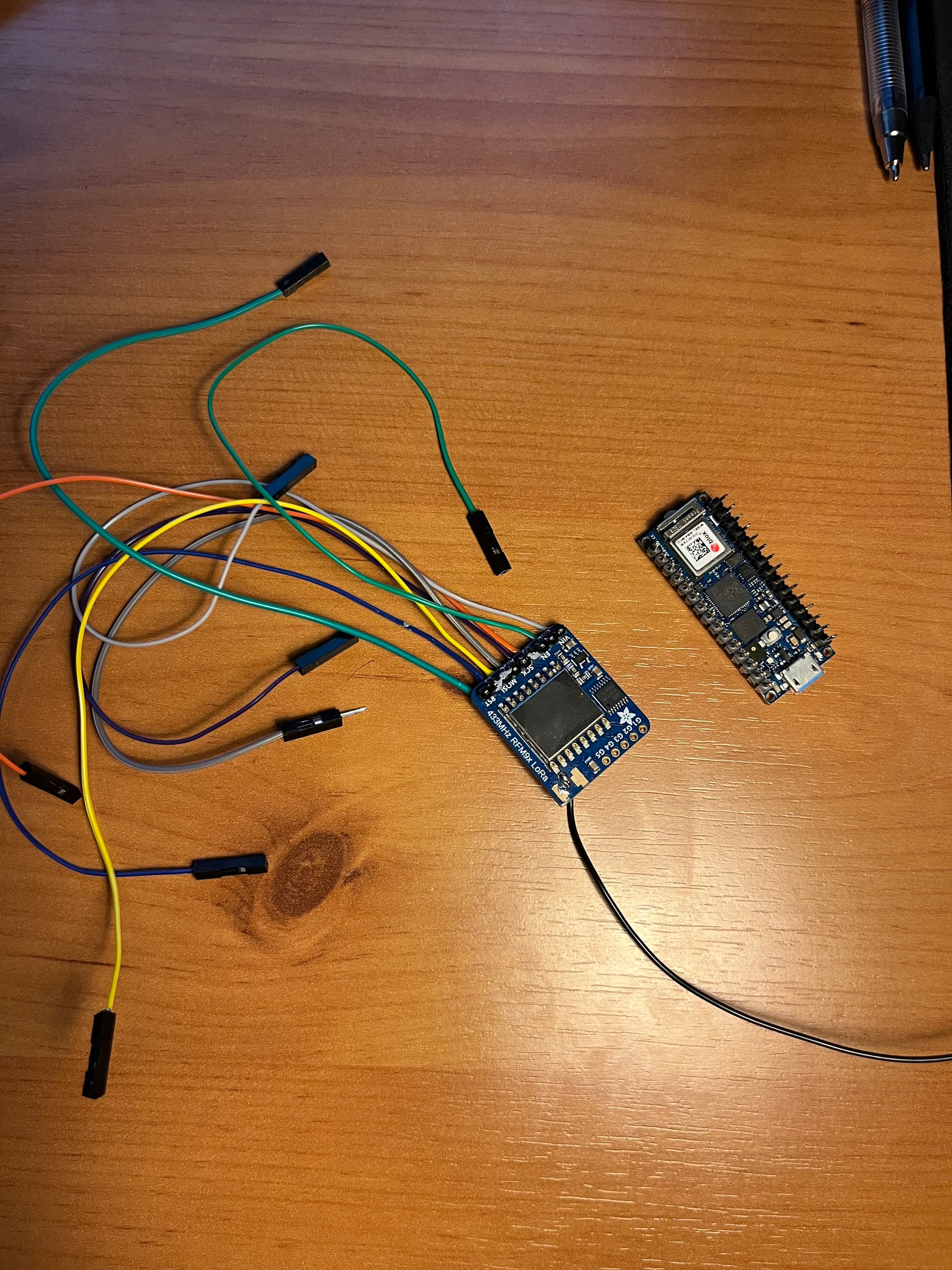
I have soldered wires onto the RMF9x LoRa module and now need to connect/solder the wires onto the arduino nanoRP2040. I do not really know for certain where to connect them. Here are some photos if someone would be kind and tell me where they are meant to go, that would be greatly appreciated. I am quite a beginner.
Many thanks, Tom

If You had posted links to their datasheets You had received a reply.
please post a photo of the module BEFORE you solder it.
Why do you not to use a pins rather than solder a wires?
First, I suggest using a breadboard and jumper wires before making solder connections to the Nano RP2040. I would consider soldering things together only when you are sure that everything works.
Now, as to the pins. The RMF9x is an SPI device. Here is a reference page.
Just search for SPI on that page.
RMF9x------------------ Nano RP2040
Vin ---------------------3.3v
SCK----------------------D13
MOSI--------------------D11
MISO-------------------- D12
CS -------------------- Any GPIO (except for A6/A7)
Well if you're determined to solder the wires to your Nano, at least solder to the back of the Nano. If later you change your mind you can simply desolder them.
I will not be surprised if that module no longer works. I rarely solder direct to the pins, I want to be able to remove a module if it fails or for any reason and doing a bad solder job on a $1 header is a lot less painful than a ruined $20 board. Watch some videos so you can see how it's supposed to be done.
I prefer someone solder a wire directly to the board than a sloppy solder joint to a pin. But I'm on your line here, and add to that - solder female strips on a perf board, so you can mount the board into those strips. Then solder of all your heart to that perf board.
AGREE 100%, I have very rarely soldered to a pin, I almost always use a female header.
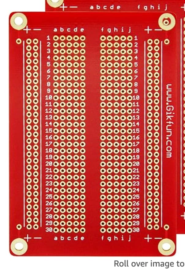
Gikfun.. where do these chinese get their ideas ![]()
No I've not seen this. Mounting holes to put onto distances or why not feet while you prototype. Nice gadget. Up until now I've used these perf boards which isn't that different from this Gikfun.
Hopefully your clean up your solder joints before powering the unit, it appears MOSI is shorted to something else, cannot see for sure. You might practice soldering a bit before working on these boards.
What does a sloppy solder joint to a pin mean
And what are strips? Sorry, I’m very new to this stuff. I’m doing this for a project
Ah these are cool, might try them
Okay sure
Oh and why do you think it wouldn’t work any longer?
Sloppy: careless, messy
Female strips (not erotic act by a woman):
when I used a RFM95 with a RP2040 I used pins
// RP2040 connections
// RP2040 SPIO0 SCK pin GPIO18  to RFM95 SCK
// RP2040 SPI0 Rx pin GPIO16  to RFM95 MISO
// RP2040 SPI0 Tx pin GPIO19  to RFM95 MOSI
// RP2040 SPI0 CSn pin GPIO 17  to RFM95 SS
// RP2040 GP20 to RFM95 Reset
// RP2040 GP21 to RFM95 DIO0
with
LoRa.setPins(17, 20, 21); // for RP2040
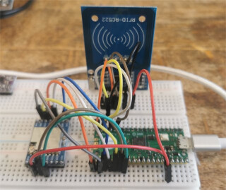
soldered pin header to PCB then used breadboard with jumper wires
photo of RP2040 wwith a RA-02 LoRa module and MFRC522 RFID
very doubtful about soldering wires to PCB
It can be done, but not the best practice, especially for beginners..
I studied the second photo a bit closer, and I can't tell if that's some sort of plastic where the wires supposedly are soldered?
using jumper wires and plugin breadboard (see photo in post 18) can lead to poor connections and intermittent problems but are a useful tool for prototyping a design
after proving such a prototype I would move to a soldered breadboard as recommended by @sonofcy in post 9 or even better a custom PCB