Good evening,
I'm working on a project with a "mega 2560 Rev3" with a "ethernet 2 Shield". I'd like to know which pins should not be used to allow SPI communication between the two devices. Writing to the SD card worked before the connections, but since I connected my 25 buttons and 25 LEDs, the communication initialization fails.
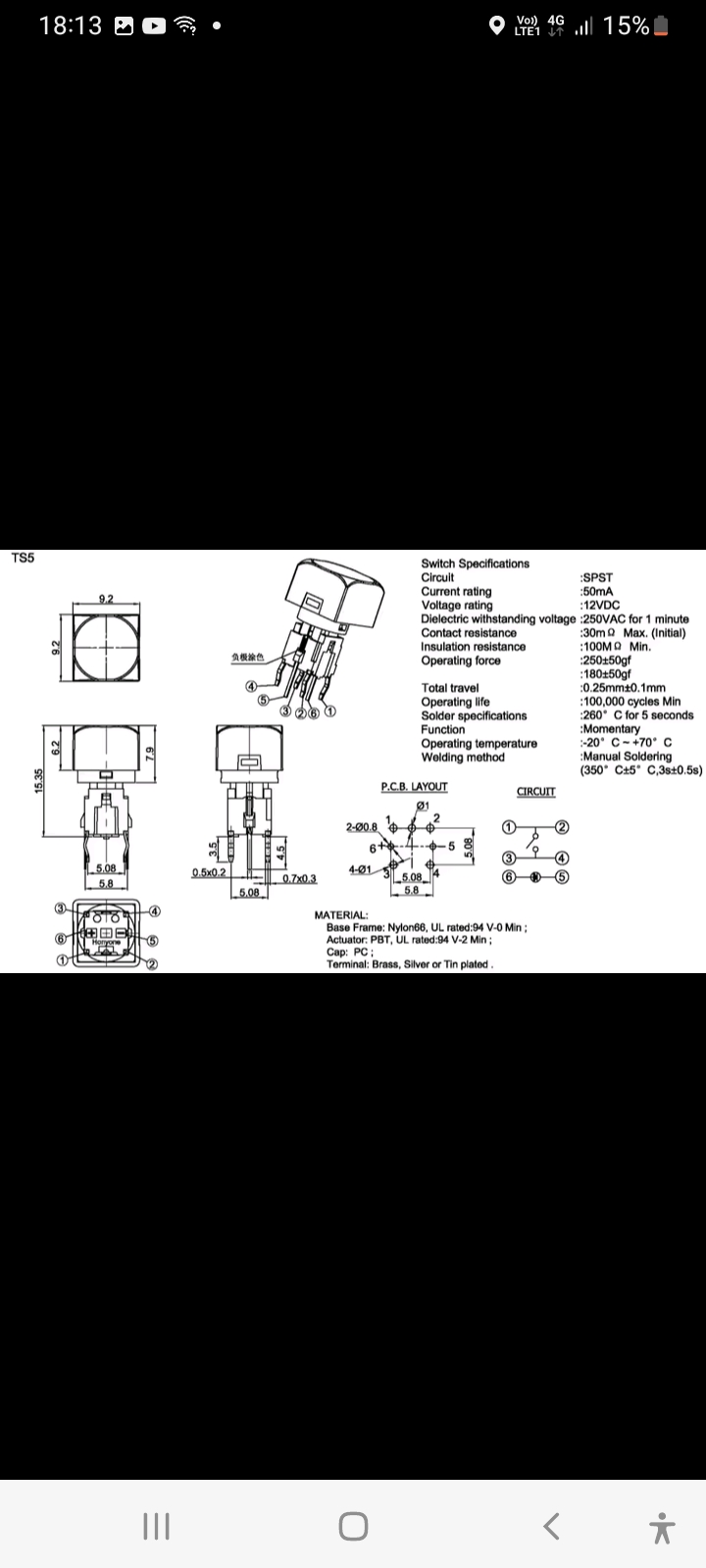
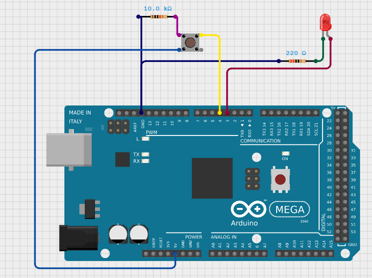
Just like normal led and push buttons... with a 10k ohm resistance for the buttons and 220 ohm resistance for led... the whole one the 5 V...
It false i know but it's work... should i change something ? It's dangerous for the mega ?
Post a simple schematic showing exactly how you have wired this and how it is powered. For the LEDs and Buttons you only need to show a few but note each pin. Also note what color LEDs you are using such as REd, Green, ..etc. and how many.
Well I have learned the hard way that all LEDs are not created equal. They can be designed to draw a certain mA and the looks and color can be deceiving.
I learned this with the UNO R4 because I needed LEDs to light up off the Renesas chip (very low mA) and well just look at some data sheets on Digikey of LEDs and you'll find they are created for lots of different scenarios. Just looking at them these days isn't enough unless you are confident in what you have laying around.
If you don't have a datasheet on the LEDs you'll have to check them with a voltmeter, ammeter, and resistor (or potentiometer).
Start with a 1k resistor it's pretty safe starting point. (Better to start too high than too low) Find how much mA they draw when they light up at a reasonable illumination level. Then compare this value with acceptable draw of the microcontroller. Datasheets are your friend.
As previously suggested you may be drawing too much current, in which case you can always use small signal transistors if needed.
The SPI pins 50-52 are just duplicated on the 6-pin header.
They internally connect to the same pins.
It seems you mistakenly thought you could just use the Mega as a LED driver.
There are current limitations to consider.
A better option could be a LED driver chip.
The MAX7219 can drive 64 LEDs and won't need any resistors for the LEDs.
Switches (buttons) are best connected between pin and ground, with internal pull up enabled on the pin. That way you won't need any resistors for your switches either.
Leo..
Yes, probably... just see for have more than 50 pins... but as asked above 190 mA is ok if the limit is at 200 mA ?
and for come back with the inital questions did you think that i make a mistake in my code ?
void sdWrite(){
    Serial.begin(9600);
  while (!Serial) {
    ; // wait for serial port to connect. Needed for native USB port only
  }


  Serial.print("Initializing SD card...");
  pinMode(53, OUTPUT);
  if (!SD.begin(53)) {
    Serial.println("initialization failed!"); //the code stop here...
    while (1);
  }
   Serial.println("initialization done.");

  //SD.remove("test.txt");
  myFile = SD.open("result.txt", FILE_WRITE);

  if (myFile) {
    Serial.print("Writing to result.txt...");
   // int a[5][5] = {{5,3,6,7,6},{1,1,1,1,1},{1,1,1,1,1},{1,1,1,1,1},{1,1,1,1,1}};


    b = ArrayToString(butUse);

    myFile.println(b);
    // close the file:
    myFile.close();
    Serial.println("done.");
  } else {
    // if the file didn't open, print an error:
    Serial.println("error opening result.txt");
  }

  // re-open the file for reading:
  myFile = SD.open("result.txt");
  if (myFile) {
    Serial.println("result.txt:");

    // read from the file until there's nothing else in it:
    while (myFile.available()) {
      Serial.write(myFile.read());
    }
    // close the file:
    myFile.close();
  } else {
    // if the file didn't open, print an error:
    Serial.println("error opening result.txt");
  }
}
Look up the Vf (forward voltage drop when on) and subtract that from 5. Use that value along with the resistor and plug into an ohm’s law calculator. That will give you the current for 1 LED. Multiply that by the number of LEDs in the circuit and that will give you the current draw.
The Arduino Mega 2560 can source is 40 mA per pin, but it is recommended to keep it below 20 mA to avoid damage. The total current for all I/O pins should not exceed 200 mA.
There is also a specification for the ports. For the ATmega2560 that is also 200 mA but for other AVR processors it's often 100 mA (e.g. ATmega2561 or ATmega328P).
Thanks for the advice! I've been looking for a driver to control 25 leds, but I've only found 4, 16, 24, and 144 channels... Does anyone know if there's anything in between?
Alternatively, in your opinion, is it easier to program two 16-channel drivers or one 144-channel driver?
And one last question: I understand I need to use SPI communication to control drivers... Is it possible to control multiple devices simultaneously using the same pins? Or are there other pins that can be used for SPI besides pins 50-53?