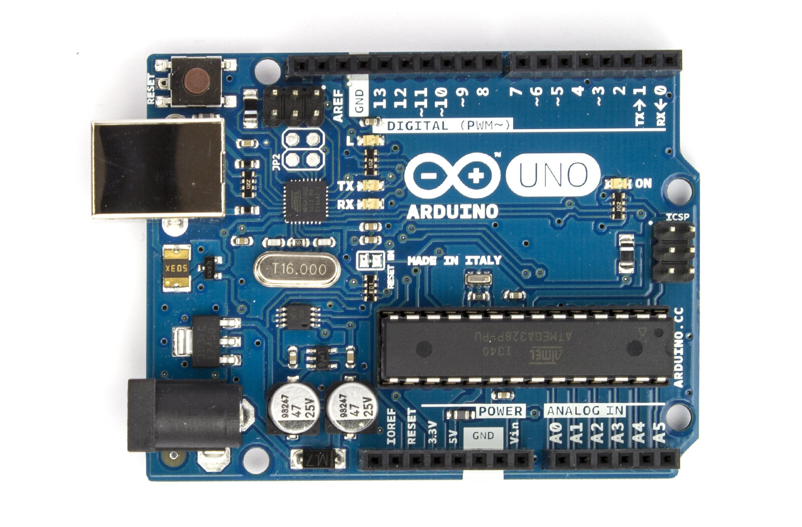
I am still thinking about the power supply for a project. I am wondering why Arduino is not build for 5V power input. Is that just because there is still the possibility to input 5V on the PIN (is that possible, BTW?), or is there a deeper reason one should design for 7-12V?
(deleted)
What he said.
The fact is that the wall wart isn't really a regulated supply and the ATMega328P and support ICs need a 5V supply that is well regulated. All regulators consume some power. So the input to the regulator is something over 5V and everything else on the board is 5V except the 3.3V pin. The schematic http://arduino.cc/en/uploads/Main/Arduino_Uno_Rev3-schematic.pdf gives the 3.3V regulator as a LP2985 and the main regulator as a NCP1117. You can bypass the NCP1117 by providing a well regulated +5V to the Vin pin and +0V to one of the ground pins.
The main regulator is the circuit marked 117-5 (5V version of NCP1117)
I assume it is because the voltage regulation uses up a volt or so as mentioned above.
http://arduino.cc/en/Main/ArduinoBoardUno
The board can operate on an external supply of 6 to 20 volts. If supplied with less than 7V, however, the 5V pin may supply less than five volts and the board may be unstable.
spycatcher2k:
You can run it on 5V using the vin pin (as long as its a regulated input - e.g. Batteries or a wall wart) - it needs the extra voltage as it has a voltage regulator on the board that consumes 1.2V of the input voltage.
Incorrect. You can run it on 5vdc by using the shield's 5V pin using an external regulated +5vdc voltage source. The Vin pin only goes to the input of the on-board 5 volt regulator and must be minimum of +7vdc if used and then the on-board regulator will power the board.
Lefty
JoeN:
The fact is that the wall wart isn't really a regulated supply ...
Certainly some are. And some are not. So be sure about the particular wall wart in question. Wall warts like this one are usually plenty good to connect directly to the 5V pin (not to the Vin pin).
What I've found that works real well for cheap is the common cell phone charger wall modules. They are regulated switching regulators, quite small and light, and usually rated a +5.1vdc @ 1 amp. I find them all the time at thrift stores for 1-2 dollars. Just read the nameplate data carefully for actual voltage, current, and connector polarity. Then just wire it to the arduino's 5V and ground shield pins.
Lefty
To be honest, I cannot think of much else what I would want to connect except those ones or batteries (e.g. 4x 1.2V AA rechargeable). Where would I have to be more careful?
Someone posted last night about a 'noisy' 5V wallwart - the noise was showing up in the PWM output signal and affecting audio results.
The other way the Arduino can accept 5V in is through the USB port. USB charger wall-warts are popping up everywhere these days, so that is an option as well.
Ok, so there really seems to be not more reason then "giving addition supoport for more and lesser quality power support".
Seems to me that for my first project, I can directly go with 5V input.
I can directly go with 5V input.
I've powered powered my arduino with ethernet shield from a 7805 regulator chip connected to a +5v pin on the arduino (also had a 10mfd capacitor on the output for smoothing).
I am not going to use a ready-made Arduino board, so my question was: Build a DC-Input e.g. 7-12V with a 7805 regulator or similar, or go with a MicroUSB port and some external 5V power source? This thread seems to suggest the latter.
ElCaron:
I am not going to use a ready-made Arduino board, so my question was: Build a DC-Input e.g. 7-12V with a 7805 regulator or similar, or go with a MicroUSB port and some external 5V power source? This thread seems to suggest the latter.
It really comes down to what power you have available, and what other devices you'll be controlling require. For example, if you're controlling 12V devices with your project it's convenient and inexpensive to start with a 12V supply and regulate it down for the ATmega, rather than boosting a 5V source.
If you're rolling your own Arduino you also have the flexibility to run the ATmega328P from 1.8V to 5.5V. You do not need to limit the design of your circuit to 5V.
Cheers ! Geoff
Sure, if you need more voltage, than you should input more voltage ![]()
I am not powering anything above 5V and 5V-MicroUSB becomes widely available, so I think that is the way to go for me. Before I am having the PCB made I will test a bit on the breadboard, complete the software and then I will present the project and ask for specific comments ![]()
