Will this Uno Project work on a Mega 2560

Hi all, new to this and not sure if it is posted in the right section.

My end goal is to take an S-Video signal (converted from RGBS) from 16 arcade cabinets and choose any two cabinets via a phone or tablet to feed into a Twitch stream for the Australian Kong Off (Donkey Kong ) competition.
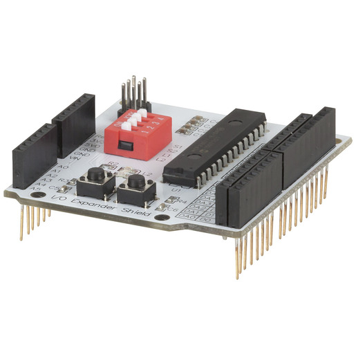
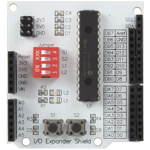
I started with an Arduino Uno (Wifi) and connected it to an Arduino compatible 8 Channel Relay Board and followed the instructions on the related project in GitHub and all worked fine.

My issue is that I need to expand the project out to 32 relays to control the PCB I have built.

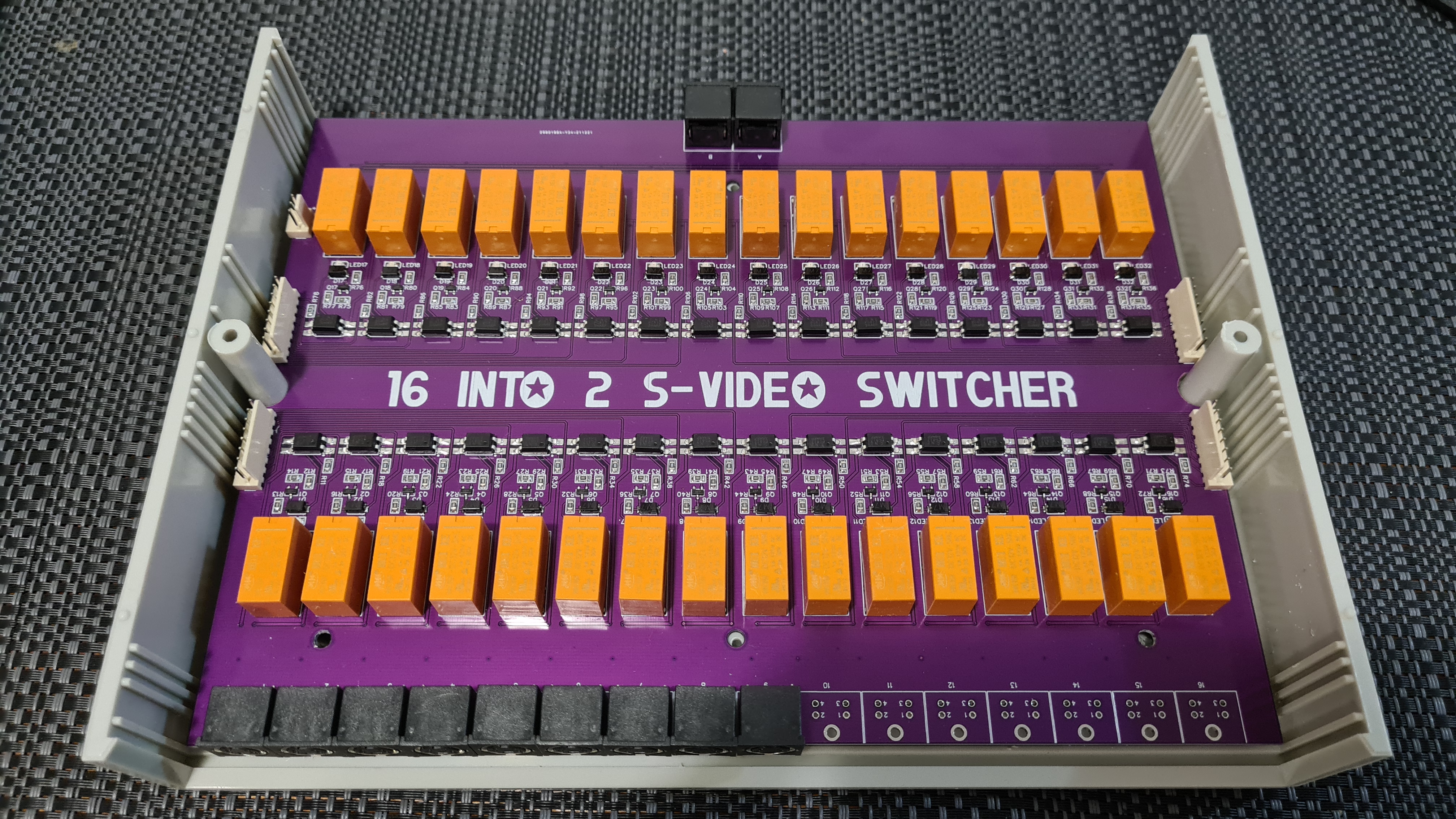
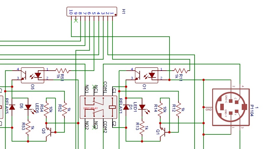
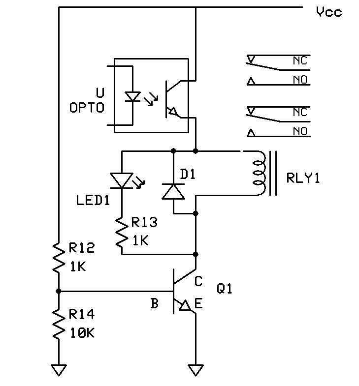
The are 16 rows of two relays, the first relay turns the input on and the second relay selects either channel A (normally closed contacts) or B (normally open contacts). At any one time there will only be three relays turned on.

So I purchased an Arduino Mega2560 (Wifi) and uploaded the project the same as with the Uno and this is where I ran into problems. I could see and connect to the Wifi hotspot with my phone but the webpage wouldn't load like it did with the Uno.
I then tried the example code that is linked with the Mega and it worked fine on the Mega as well as the Uno.

Example Code:
Arduino:

#define SERIAL_BAUD 115200

/*******************************************
	In this code we have used "[]" to surround our command codes
	As a bit of a proof of concept for how to use the XC4411 board
*********************************************/
const int led_pin = 13;

String receivedCommand = "";
bool dataIn = false;

void setup()
{
	// put your setup code here, to run once:

	Serial.begin(SERIAL_BAUD); //same as ESP baud
	pinMode(led_pin, OUTPUT);
}

void loop()
{
	// put your main code here, to run repeatedly:

	while (Serial.available())
	{
		char c = Serial.read(); //read it

		if (c == '[')
		{
			//this is the start of the command string
			receivedCommand = "";
			dataIn = true;
		}
		//otherwise, we are still reading the command string:
		else if (dataIn && c != ']')
		{
			receivedCommand += c;
		}

		else if (dataIn && c == ']')
		{
			//finished receiving the command, process it
			Serial.print("XC4411 has been running for ");
			Serial.print(millis(), DEC);
			Serial.println(" milliseconds..");
			 Serial.print("Received command was '");
			Serial.print(receivedCommand);
			Serial.print("' - action: ");

			if (receivedCommand == "LEDON")
			{
				Serial.println("TURN LED ON");
				digitalWrite(led_pin, HIGH);
			}
			else if (receivedCommand == "LEDOFF")
			{
				Serial.println("TURN LED OFF");
				digitalWrite(led_pin, LOW);
			}
			else if (receivedCommand == "LEDTOGGLE")
			{
				Serial.println("CHANGE LED");
				digitalWrite(led_pin, !digitalRead(led_pin));
			}
			Serial.println("---------------------------------------");
		}
	}
	delay(10);
}

ESP Code:


#include <ESP8266WiFi.h>
#include <WiFiClient.h>
#include <ESP8266WebServer.h>

#define SERIAL_BAUD 115200 //make sure this is the same in arduino.ino

ESP8266WebServer server(80);

String serialData = "";

//this is our HTML website that we send to the user, much easier to use SPIFFS in future.
const String html_page = "<!DOCTYPE html>"
												 "<html>"
												 "  <head>"
												 "    <meta name='viewport' content='width=device-width, initial-scale=1.0' />"
												 "  </head>"
												 "  <body>"
												 "    <a href='/ledon'>turn LED on</a>"
												 "    <a href='/ledoff'>turn LED off</a>"
												 "    <h1>Latest data from arduino:</h1>"
												 "    <pre id='reading'></pre>"
												 "    <script>"
												 "      (function() {"
												 "        /* get new data every second*/"
												 "        setInterval(function() {"
												 "          fetch('/reading')"
												 "					.then(response => { return response.text();})"
												 "					.then(text => {"
												 "            document.getElementById('reading').textContent = text;"
												 "          });"
												 "        }, 100);"
												 "      })();"
												 "    </script>"
												 "  </body>"
												 "</html>";

const IPAddress serverIPAddress(10, 0, 0, 7);

void setup(void)
{

	Serial.begin(SERIAL_BAUD);

	//here we set up as a hot spot, called XC4411 dual board
	WiFi.softAPConfig(serverIPAddress, serverIPAddress, IPAddress(255, 255, 255, 0));
	WiFi.softAP("XC4411 Dual Board example code");

	//here we set server paramters, the main page is the html_page from above
	server.on("/", []() { //send html code, from above
		server.send(200, "text/html", html_page);
	});

	//reading is just a copy of the serial Data
	server.on("/reading", []() { //send raw serial data
		Serial.println();
		Serial.println(serialData);
		server.send(200, "text/plain", serialData);
	});

	server.on("/ledon", []() {
		Serial.println("[LEDON]"); //send serial data to arduino
		server.send(200, "text/plain", "ok");
	});
	server.on("/ledoff", []() {
		Serial.println("[LEDOFF]"); //send serial data to arduino
		server.send(200, "text/plain", "ok");
	});
	server.on("/ledtoggle", []() {
		Serial.println("[LEDTOGGLE]"); //send serial data to arduino
		server.send(200, "text/plain", "ok");
	});

	server.onNotFound(handleNotFound);
	server.begin();
}

void loop(void)
{
	while (Serial.available())
	{
		char x = Serial.read();
		if (x == '\r')
			continue;
		serialData += x;
	}

	server.handleClient();
}

void handleNotFound()
{
	String message = "File Not Found\n\n";
	message += "URI: ";
	message += server.uri();
	message += "\nMethod: ";
	message += (server.method() == HTTP_GET) ? "GET" : "POST";
	message += "\nArguments: ";
	message += server.args();
	message += "\n";
	for (uint8_t i = 0; i < server.args(); i++)
	{
		message += " " + server.argName(i) + ": " + server.arg(i) + "\n";
	}
	server.send(404, "text/plain", message);
}

I have spent a couple of days trying to get the 8 Channel Relay project to work on the Mega without success, any thoughts?
I have a feeling it has something to do with the serial ports i.e. the Mega has 4 and the Uno only has one??

Please post a link to where you bought it from so we can be sure we understand what it is.

From the project link, it looks like the original "Uno (Wifi)" you mentioned is this board:
https://www.jaycar.com.au/uno-with-wi-fi/p/XC4411
Is that correct?

Yes, both bought from Jaycar and both Uno and Mega have onbaord Wifi.

Uno code:


// Uno portion of WiFi Relay Controller Project 

// make sure this matches esp
const long serial_baud = 115200;

//quick debug macros, so you can test with serial monitor
//first line prints to serial, second does nothing
//either one will have to be compiled
//#define D(...) Serial.println(__VA_ARGS__);
#define D(...) 


const int relay_start = 2;
const int relay_length = 8;
const int status_led = LED_BUILTIN;


void setup(){

  Serial.begin(serial_baud); 

  for(int i = 0; i < relay_length; i++){
    pinMode(relay_start + i, OUTPUT);

    D("set relay on pin")
    D(relay_start + i)

  }

}

void loop(){

  /*command packets are in the form of:
    >Ha 
    
    > - start command 
    H - hex digit of relay ( 1 -> 16), '1' to '8' is what we need
    a - activate, will leave on until it reaches
    c - close, or any other character in this place
  */


  //this will skip until read reaches '>'

  while(readSerial() != '>' )
    continue; 

  D("read >")
  //now we have already read '>'
  //next character will be the relay
  char relayCharacter = readSerial();
  int relay = charToRelay(relayCharacter);

  D("RelayCode:")
  D(relay)
  //error code
  if ( relay == -1){
    //skip this one, start loop again
    return;
  }

  //now the final character should be the mode 
  char modeCharacter = readSerial();

  //"inline if" statement, is it 'a' ? make mode HIGH else LOW;
  int mode = (modeCharacter == 'a')? HIGH : LOW;
  D("Mode: char")
  D(modeCharacter)
  D("Mode: bool")
  D(mode)

  //then finally run it and loop again

  digitalWrite(relay_start + relay, mode);
}

//simple 'blocking' function to wait until we receive something
char readSerial(){
  while(! Serial.available())
    continue;
  return Serial.read();
}

int charToRelay(char incoming){

  if (incoming >= '0' && incoming <= '9' ){
    //just a standard digit;
    return incoming - '0';
  } else if ( incoming >= 'A' && incoming <= 'F'){
    //hex digit
    return incoming - 'A' + 10;
  } else {
    //out of range, not good
    return -1; 
  }
}

Esp Code:

#include <ESP8266WebServer.h>
#include <FS.h>

// Web server to serve our app
ESP8266WebServer server(80);
IPAddress serverIP(1, 0, 0, 1);

//another define bunch
//similar to the uno code
//#define D(...) Serial.println(__VA_ARGS__);
#define D(...)

const long serial_baud = 115200;

void setup()
{
  Serial.begin(serial_baud);
  D("Starting")
  SPIFFS.begin();
  // setup a new hotspot, no password
  setupHotspot("Relay Controller");

  server.on("/relay", sendRelay);
  server.onNotFound(searchFileSystem);
  server.begin();
}

void loop()
{
  server.handleClient();
}

void setupHotspot(const char *SSID)
{

  WiFi.mode(WIFI_AP);
  //WiFi.begin(SSID); //connect to some network
  //WiFi.softAPConfig(serverIP, serverIP, IPAddress(255, 255, 255, 0));
  WiFi.softAP(SSID);
  // todo: add a timeout?
  D("Created soft AP called")
  D(SSID)
  D(WiFi.softAPIP())
}

void sendRelay()
{
  const String relayString = server.arg("relay");
  const String modeString = server.arg("mode");

  if (relayString == "")
  {
    server.send(404, "text/plain", "No relay arg");
    return;
  }

  if (modeString == "")
  {
    server.send(404, "text/plain", "No mode arg");
    return;
  }

  //we have a relay and a mode; let's work on them
  short relay = relayString.toInt();

  if (relay < 0 || relay > 7)
  {
    server.send(500, "text/plain", "Relay out of range");
    return;
  }

  char mode = modeString.equals("activate") ? 'a' : 'd';

  //send this to the UNO
  Serial.write('>');
  Serial.write('0' + relay);
  Serial.write(mode);

  //we send a response to the web-app
  server.send(200, "text/plain", "OK");
}

// ---------------------------------------------------------------------------
void searchFileSystem()
{
  //server.uri() is the param accepted; ie:
  //    http://10.20.30.40/somefile.txt - uri is /somefile.txt
  // we will put it into a string for the string utility functions

  D("Calling filesystem with")
  D(server.uri())
  String filepath = server.uri();

  if (filepath.endsWith("/")) //is this a folder?
  {
    filepath += "index.html"; //index page of the folder being accessed
  }

  if (SPIFFS.exists(filepath))
  {
    String contentType = getFileContentType(filepath);

    File fp = SPIFFS.open(filepath, "r");
    server.client().setNoDelay(true);

    server.streamFile(fp, contentType);
  }
  else
  {
    Serial.printf("%s was not found, plaintext response", filepath.c_str());
    server.send(404, "text/plain", filepath + " File not found, have you uploaded data to the ESP correctly?");
  }
}

String getFileContentType(String &filepath)
{

#define FILE_MATCH(fp, ret)  \
  if (filepath.endsWith(fp)) \
    return ret;

  //got the following from:
  //https://stackoverflow.com/questions/23714383/what-are-all-the-possible-values-for-http-content-type-header
  FILE_MATCH(".html", "text/html")
  FILE_MATCH(".txt", "text/plain")
  FILE_MATCH(".css", "text/css")
  FILE_MATCH(".js", "application/javascript")

  // the following is provided as a "just in case" -
  // it doesn't hurt to include them, but we haven't used them in this project (yet)
  FILE_MATCH(".mp4", "audio/mpeg")
  FILE_MATCH(".jpg", "image/jpeg")
  FILE_MATCH(".png", "image/png")

  //at the very least just return something
  return "text/plain";
}

// -- Macro definitions -----------------

// --------------------------------------

Hi,
Did you look for an I/O expander to use with the UNO?

Tom... :grinning: :+1: :coffee: :australia:

There was one available from Jaycar (Expander I/O Shield for Arduino/Pcduino) but it only expands by 16 pins, I needed a total of 32 so I'd be short by at least 2 pins.

Hi,
This from Jaycar;


I think ou can stack them and have 32 I/O, they are I2C and by the looks of it you can set each shield address there own address.
Personally I would be constructing a vero/strip board module with 2 x MCP23017, to give you 32 I/O.

Can you please tell us your electronics, programming, arduino, hardware experience?

Thanks.. Tom... :grinning: :+1: :coffee: :australia:

Thanks Tom, my electronics experience is reasonably good and specialize in repairing 1980's arcade game PCB's and have designed and built PCB's including the one in the first post.
I have virtually no coding experience and am learning as I go.
The MCP 23017 looks like an option, building a PCB on vero or custom designing a PCB won't be an issue, just working out the code is where I'll struggle.

Hi,
There are libraries for the MCPs, with some very basic examples that would cover what you want to do.
May be a way out if the Mega option becomes a big hassle.

Tom.... :grinning: :+1: :coffee: :australia:

I'll look at these as options.

My original question is will the relay controller code work on a Mega and if not, what needs to be modified?

How could that be a problem?

Personally, I find the UNO and Mega 2560 format very tedious to use, restricting you to use whatever "shields" are available.

Doesn't look like it to me. The "expanded" pins are brought out on headers just inside the UNO header set, making it particularly difficult to connect to them if you mount a second board on top.

Kaizen, you have failed to give us the schematic - at least the individual module circuit - for your switcher. Can't say I would use relays for this if I were to do it, but we need to know how you propose to connect port expanders and such to your board; does it have driver transistors for the relays?

And if you are buying parts form Jaycar, you clearly must be in a hurry as you are paying a premium of several times. OK, it is nice about Jaycar that if you are in a hurry, you can nip over and grab something if it is in stock - which that expansion board is not at this moment. :roll_eyes:

And if you want WiFi, the "Arduino" hybrids are a bit cumbersome. Prsumably you "talk" to the ESP over one of the additional hardware ports on the Mega 2560, using the "AT" commands.

I would expect to do the whole job with an ESP - an ESP-01 if you do not need any other major interface - using a couple of cheap port expanders or four TPIC6B595s if you need them to drive the relay coils directly.


This is one of the individual module circuits used to switch the relay.

I had initially planned to daisy chain four 74HC595 Shift Registers to get 32 output pins then saw the Mega had enough pins and wifi onboard to do the job all in one unit.
I just can't see/understand why the code won't work on the Mega, the webpage loads partially but never completes to where the buttons are activating.

Hi,
Just looking at your schematic and rearranging the layout;


What is the function of Q1?

Thanks.. Tom... :grinning: :+1: :coffee: :australia:

Hi,

What are you using to connect the webpage, what is your WiFi connection?

Tom... :grinning: :+1: :coffee: :australia:

Yep, that is indeed it as shown - which is total nonsense!

That would be completely unworkable. Even if we accept a drafting error and the optocoupler is actually in the base circuit of the transistor, if the optocoupler diode cathode is connected to the same negative "ground" as the transistor, then any "isolation" provided by the optocoupler is quite meaningless. :roll_eyes:

I'm self taught and still learning...
After looking at what you said, I agree there is no isolation however the relay is only switching an S-Video signal and not dangerous high voltage so it's not an issue in this instance. The circuit has been tested and it will switch the relays on nevertheless.
So my original question "Will this Uno Project work on a Mega2560" has not been answered yet which is all I needed to know.
I went back to Jaycar and bought another Mega2560 as I had a feeling there was something wrong with the one I was having difficulties with.
I uploaded the code for the Wifi Relay Controller and it worked fine, seems there was something wrong with the Mega2560.
So to answer my own question.. YES the code for this project will work on both the Uno and Mega2560.
Now I just need to work out how to expand it to work with 32 relays, I might start another thread for that.
Thanks for those who replied witch constructive comments.

That is not the issue. The issue is that circuit - if it is truthful - is nonsense! :worried:

Hi,
Can you post link to spec/data of the relay?
Can you post link to specs/data of the Opto?
What voltage is Vcc?

Who designed the circuit?

Thanks.. Tom... :grinning: :+1: :coffee: :australia:

Hi, I am confused.
The circuit you posted in post#12 is to interface with this board?
OR
Is it this board?

Tom... :grinning: :+1: :coffee: :australia:

This topic was automatically closed 180 days after the last reply. New replies are no longer allowed.