I am fairly new to using Arduino and I don't have huge amounts of experience in electronics.
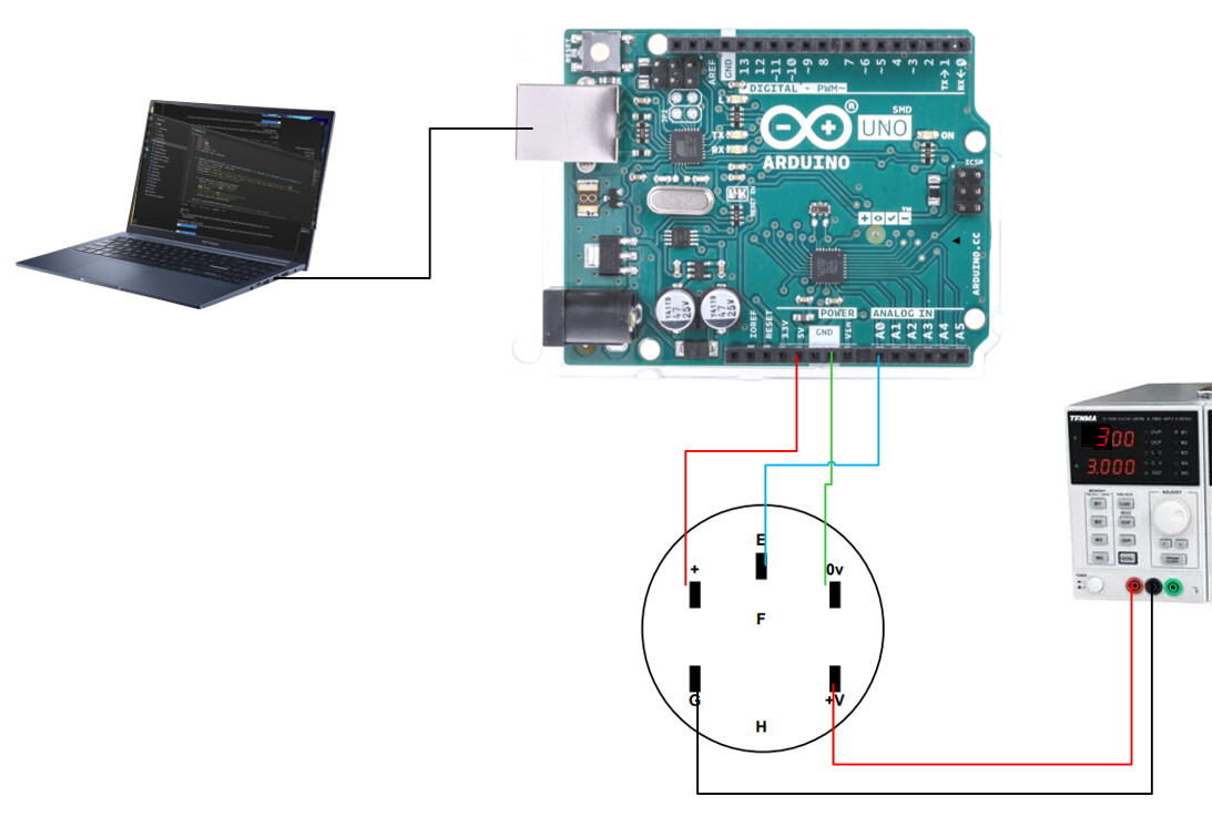
I am trying to wire up a turbine flow sensor (datasheet) to an Arduino Uno and collect the data but I am not sure how to do the wiring for it. I have attempted to wire it up (see wiring diagram) but I am not getting any results. From the datasheet, I am assuming the sensor needs two separate power sources (one is for the LED).
I have tried: getting both from the Arduino Uno (5V and 3.3 V) as well as getting the 5 V from the Arduino and 3 V from a power supply, the latter is what's shown in the wiring diagram.
Is the wiring diagram correct?
I am not getting any signal, and I now think it might be because this sensor doesn't output analogue. How can I get the Arduino code to read a digital output? Does anyone have a code for this?
Not only am I connecting the turbine flow sensor but there will also be 5 pressure sensors connected to the Arduino so I do need to be able to get some analogue results.
Again, I'm fairly new so I'd be very grateful for any tips and/or thorough explanations.
If you connected the power supply to the LED without any current limit (resistor) you may have already burned the LED. Did you limit the LED current?
It appears that the output of the meter is a digital pulse train with frequency proportional to flow. There are several libraries available to help measure frequency.
There is nothing to suggest it might be analogue, and a lot to suggest it is just another digital pulse device, and all you have to do is count them. See page 3.
I have no idea why the built-in LED should be so critical as to require an exclusive power supply but all you need do is ensure it is within the spec provided, and Uno can do that.
There is a bazillion examples of flow meters out there in Arduinoland. I use a stripped down version of this.
Maybe that fancy power supply has current control but, if you can't see the LED, and never could, you should start by checking continuity.
I have never used a meter like this, but while reading the docs I saw that the intensity of the LED (current) may need to be adjusted to penetrate the fluid with enough brightness.
By ' Uno can do that', do you mean the 3.3 V power supply should work even if the LED requests up to 3 V?
Thanks for the flow meter link. Would the code in the link you provided work for my flow meter if I wanted to get a digital output? What baud rate do you recommend (or does it not matter much)?
All I meant was that, whatever configuration you use, Uno is capable of powering a LED. That includes using the 3.3v pin. I fail to see why there should be a 3.0v maximum, and I don't believe it either. That said, a voltage divider on the 3.3v pin means just an additional resistor. I imagine 'Fungus is right and, assuming you are using water, you need a minimum brightness from the LED, and a 600r/1.2k divider may suffice, thereby giving you 2.2v. There is better information on LEDs in the Arduino reference.
I don't know what you mean by digital output. I know there are issues with serial output but there are examples using the same counting principle that print to serial monitor OK. I guess they use 115200.
By continuity, I mean using a meter to check that the LED is not fried.
You need to see if LED has been damaged. Check continuity of the LED citcuit using the diode range of your DMM. Connect the DMM red lead to LED (V+) and black to ground or common. You should read continuity (anout 3V). Reverse the leads and it should read open. If it reads open both ways, the LED is probably burned.