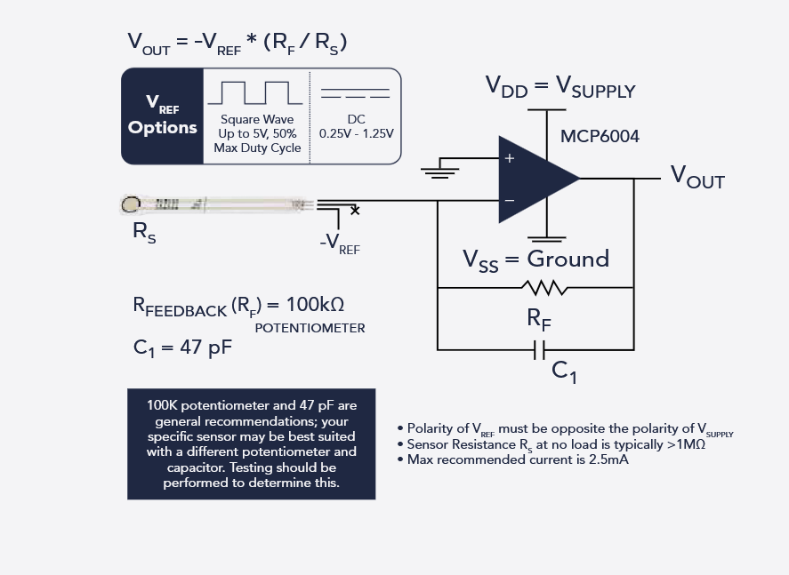
I'm trying to hook up a Tekscan FlexiForce ESS102 pressure sensor to my Arduino Uno, and I'm following the recommended circuit diagram from their datasheet (which uses an MCP6004 op-amp).
My goal is to use the recommended circuit with the ESS102 sensor (RS), a 100kΩ potentiometer (RF), and a 47pF capacitor (C1) to get a voltage output proportional to force on the Arduino's A0 pin.
I understand the simpler voltage divider circuits often shown for basic FSRs , but this recommended circuit requires a negative reference voltage (-VREF) applied to the sensor (suggested magnitude around -0.25V to -1.25V). This is where I'm getting stuck!
Why the Negative VREF? I understand how a simple voltage divider that uses the Arduino's +5V would work. Can someone explain in simple terms why this specific op-amp circuit needs a negative voltage applied to the sensor? Is it really necessary for getting a better reading compared to just using a voltage divider?
How Do I Get Both Voltages? This is the main problem. I need +5V for the Arduino and the MCP6004 op-amp (which I can get from USB/Arduino's 5V pin), but how do I also reliably get a small negative voltage like -1V?
I currently only have the Arduino USB power / a basic 5V wall adapter, and a cheap bench supply.
I'm just really fuzzy on integrating that negative voltage source correctly alongside the standard 5V stuff.
You can use a battery to create a negative voltage, but it's important to understand that voltage is always relative to a reference point. Think of it like a map—depending on where you’re standing, you can go north (+) or south (−). If you're already at the North Pole, the only direction you can go is south.
In electrical terms, if you connect the battery properly and use +5V as your reference (connecting your black meter lead there), then ground will appear as −5V, and a −1V point relative to ground will appear as −6V from your reference. The −1V is defined with respect to ground, but since your reference is +5V, the reading shifts accordingly.
The Tekscan "electrical integration guide" shows the difference between the two (actually there are three) approaches. The resistor divider approach is quite non-linear (but depending on your application, it may be good enough.)
There are ready made ICs that can supply small negative bias voltages from a positive supply but I can't remember part numbers.
Wait for member @jim-p to arrive, bet he knows.
Because it is an inverting amplifier circuit. The polarity of a signal applied to the minus input will be inverted, positive signals will become negative and negative signals will become positive. So to get a positive voltage signal output, the input must be negative, hence -Vref
You may now say, I don't care if it positive or negative, so I'll use a positive Vref. Well since the opamp only has a positive supply voltage (Vdd) it can only output positive voltages. To output negative voltages you would need a positive and negative supply voltage. In your diagram and with a different opamp, you could make Vdd = +5V and Vss = -5V (not ground) and Vref can now be +1.25V. However, an Arduino can only input positive voltages, so the original circuit makes sense.