hey every one, i hope someone can help me with this.
i do have 16 led arrays, with different lengh's ( shorteste 23 led's and the longeste 93 led's ), and every led array is connected to a tlc5940 channel.
My problem is that i just cant power 93 led's hooked in series ( it need's to much power ). and as far i understand i cant connect the led's in parallel since it is not going to work with the tlc5940.
any suggestion on to solv this the smartest way ? .. please any suggestion will be appreciated.
the voltage i am using, is 24 V, 10 mA .... but as far as i understand i just cant power more than 10 Led's in series with 24 volt.
any suggestion how to do it ?
yeah exactly 316 v is way too much ... so that's why i dont know what to do .
here is what i am trying to do :
i have a poster panel with some quotes, and i am trying to lightend the quotes with Led's. every quote is different, and then has a different length, so the shorteste quote can be lightend with 23 led's and the longest one with 93 led's.
the led arrays will be lightend in random fashion, in fading way ( in and out ).
i have 30 quotes in total, that's 30 led arrays with different lengths, to control these i am using 2 TLC5940 hooked in parallel, and every Led array is hooked to a channel.
when lightning a "quote" the hole array should lighten up ( fade in and out ).
to control these i am using 2 TLC5940 hooked in parallel, and every Led array is hooked to a channel.
You don't have enough current capacity in a TLC5940 to drive even the shortest string of LEDs, 20mA x 23 is 460mA and the longest will take 1.86 Amps. You can only get 120mA per channel on this chip and that is pushing it. With the power dissipation limits this is more like 60mA.
So first off you need a bigger power supply.
You can implement a system like KE7GKP described but due to the current you are going to have to switch you should use FETs for both the top drivers (p-Chanel ones) and the bottom one (n Channel).
You also need a resistor in series with each LED to control the current.
Thanks for the help ... before posting s a shematics i would like to clarify some things, juste to make sure that i understand correctly.
can i fade Led's in and out with shift registers ? because i thought that i can only turn then on and off ?
is 74HC595 good enough, or should i use some high voltage shift registers like tpic6b595
every shift register has only 8 channels - maybe a dumb question, but just trying to learn here - but can i hook a hole array to a shift register, i mean every led array has alot of led's.
is the setup "KE7GKP" suggested, a kind of multiplexing ?
This all seems pretty simple to me. Just make each of your strings and attach them to a power mosfet. Attach the bases of the mosfets to the outputs on the tlc5940. This way your using the mosfets as an electrical switch for a higher power load. Calculate the power requirements for the whole thing and get one power source big enough for the whole thing. Then use the led calculator or just do the math to figure out what resistors and arrangement you need.
Thanks alot for the explanation .. that made things clear for me.
for instance i want to light up one array at a time.
but i still have an issue ... because actually using a mosfets with a couple of TLC5940 was my original setup ( i already programmed the thing ). my problem with that setup was powering the whole thing. i mean if i am going to use an array pr. channel ( for the tlc5940 ) i need to have those Led's in series. and having 93 led's in series need a lot of voltage ( more than 300 v ).
if this solution is the simplest, how can i deal with the powering issue ?
This all seems pretty simple to me. Just make each of your strings and attach them to a power mosfet. Attach the bases of the mosfets to the outputs on the tlc5940
It is not so easy because if you invert the signal output you will never be able to turn any LED off completely.
Thanks for a great explanation man . really appreciate it.
last question though, i already bought some N-channel mosfets ( FQP1306 http://sm0vpo.com/_pdf/FQ/FQP13N06.pdf ) and i've been reading the http://focus.tij.co.jp/jp/lit/an/slva280/slva280.pdf. and as i understood it works the same way as the transistor you mentioned, and will be wired the same way. I can though see the idea in your suggestion, the price is much more cheaper.
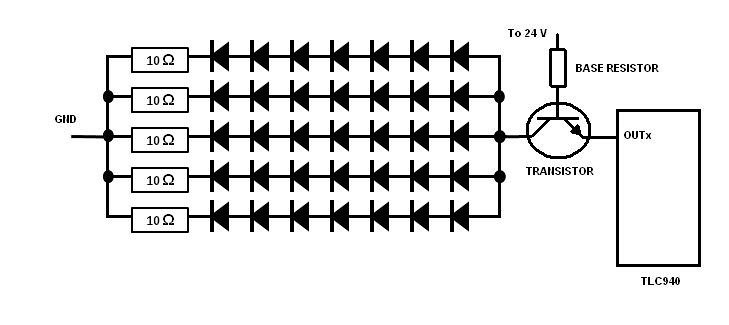
i drawed a wiring based on your explanation, is that correct ?
@KE7GKP
Yes but with that circuit V+ can only be +5V, any higher and you can't turn the transistor off, and +5V is not enough to run more than one LED. So no series wiring, it will have to be parallel with a resistor for each LED.
@stregoi
No that circuit is all wrong, the TLC will only sink current so there is no way for the LEDs to get any current.
@Grumpy_Mike
now i am kind of confused .. i've been told in a earlier post that i cannot use led's in a parallel wiring with the TLC5940. and that no need to use a resitor for every led.
how should i understand this ?
In which case when it is off you are presenting the TLC5940 with 24V, this chip has a maximum voltage rating of 17V and so you will blow it up and it will not work. There is an application note to tell you how to use higher voltages it's number is SLVA280.