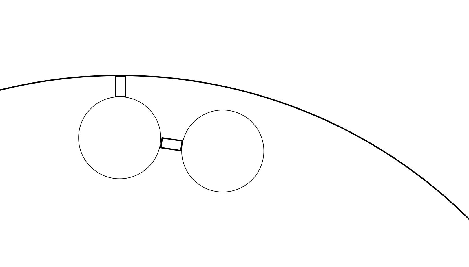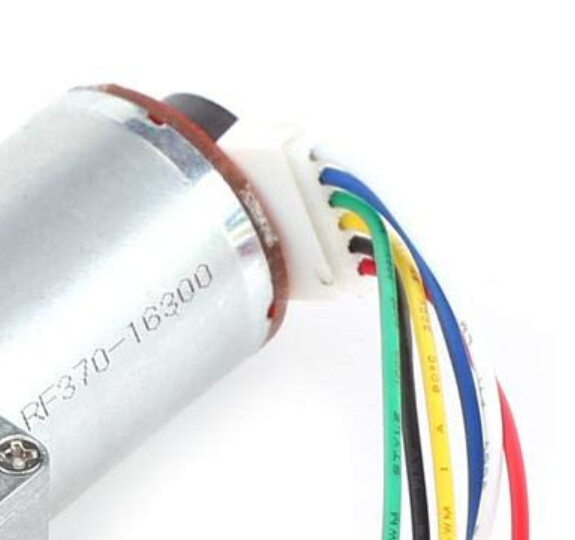
If this is what you have, I'm most sure you can follow the black and white image I showed earlier.
Black to GND
Blue to 5V or VIN
Yellow to one digital pin
Green to another digital pin
So the red and white go to your motor driver. You set the speed and direction of the motor by sending the right signals to your motor driver. That depends completely on what kind of driver you have. Usually you send digital LOW to one pin and a PWM to another pin. The PWM determins the speed. Switch the LOW and PWM pins to make the motor go in the other direction. All this has nothing to do with the four other wires. Those you need to keep count of how much the motor has rotated. You create the logic for that in your program. Although I bet there are libraries for that.
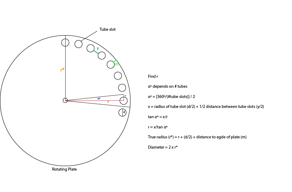
Your ratio is 20/60. So when your small pulley makes 60 turns, the big plate makes 20 turns. 3 turns to 1 turn.
Looking at this:
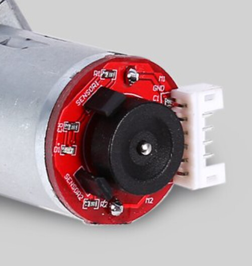
...it seems there are two Hall sensors next to the motor axis. I bet you get one pulse per revolution of the motor axis. Somewhere was mentioned 20 pulses per revolution. That would be the shaft, after a 1:20 ratio of the worm gear. So 3 revolutions means 60 pulses, and one revolution on the big plate. 60 pulses, 360 degrees on the big plate. 1 pulse is 6 degrees. Your 26 evenly distributed openings would be 360/26 or 13.85 degrees per opening. With 30 openings you would get 12 degrees or 2 pulses per opening. Just saying.
I might have calculated something wrong. And I'm not sure about the worm gear ratio.