Add another Schottky diode across the pull up resistor, cathode to 3.3volt.
I still would use an opto coupler here. Just one could do.
Diode-OR could drive the opto LED with a 1k current limiting resistor.
Opto transistor between pin and ground of the MCU, with internal pull up.
Leo..
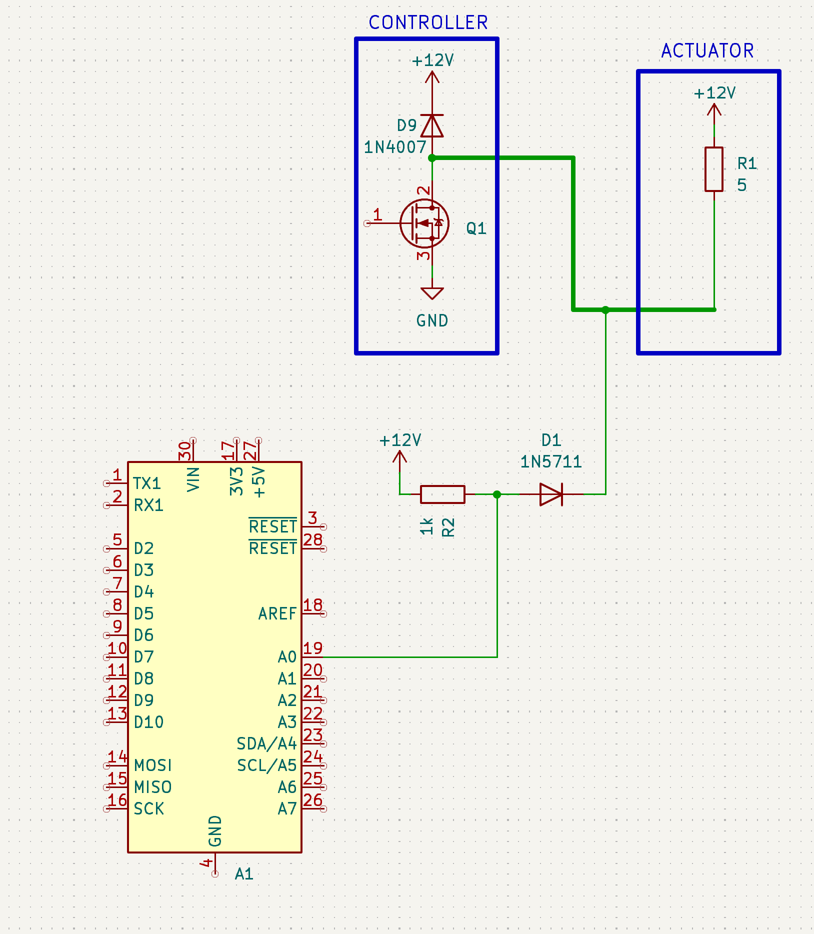
Pull-up is 1k, 6 diodes with 3 ohm "actuator" resistors each
But it would also not open immediately, I believe, so is there a sense?
The next iteration of the device would definitely use opto-coupler, you have convinced me
My solution has too many "if"s
Turn-ON time of a diode is in the nano second range, and about the same for normal and Schottky. Only turn-OFF is very different, and the only spec you will find in datasheets.
Leo..
Seems right. Schottky turn-ON/OFF times are very small. Only normal diodes have a delayed turn-OFF time. Nano/pico is seems irrelevant here with wires and breadboards being part of the equation.
Leo..
When the MOSFET turns OFF the coil's magnetic field will collapse, trying to push current downward toward the MOSFET drain and diode which will not conduct in that direction (the bottom of the coil is now positive with respect to the top), so voltage will build until something gives, either the MOSFET or the diode, A0 pin.
The kickback voltage is positive at the drain relative to source, the "body" diode is reverse biased, if its a zener it will conduct at some voltage but can it react fast enough and at a voltage low enough to prevent the gate insulation from blowing?
Not good. It may be OK it may not. You may find your arduino working fine for a while then mysteriously fail.
I'd look for a safer solution such as optocouplers.
Connecting a high voltage to an Arduino without galvanic isolation can be done with careful circuit design. However there will be a trade off on circuit complexity between the two approaches.
Firstly- want to confirm, that the setup discussed did it's job great in a prototype board
But I still want to do it the right way in a "release" board. The optocoupler way
Could you, guys, please, confirm I got it right. My setup seems to be a little exotic, so better safe, then sorry