I also have some more questions: Do light strings like these have built-in resistors and capacitors? Will I have to lay out some of this stuff on a breadboard?
Thanks ![]()
I also have some more questions: Do light strings like these have built-in resistors and capacitors? Will I have to lay out some of this stuff on a breadboard?
Thanks ![]()
Basically yes they have, There is a ws2811, 4 resistors,1 for each channel and 1 for the ws2811 itself, a 100nF capacitor for the ws2811 power input (beyond the resistor)
But as extra 470uF capacitor for the first pixel on the 12v line is recommended.
![]()
I have a similar power supply like that. Those outputs probably aren't independent. They are just places to connect wires. V+ is what it says V- is actual GND,
and there should be 3 terminals for the AC input . Load , N (for neutral) and the earth symbol, which can be connected to the earth terminal of the wall socket.
The V- is called what it is called to prevent a mix-up there.
Yes and no! It should not, but for the problem Deva_Rishi explains. ![]()
Well, supplies for two independent 12 V outputs are exceedingly uncommon!
No, it is called "V-" because it is the supply negative. It is not ground!
Pedantic city here @Deva_Rishi and @Paul_B
The terminals are not marked V- they are marked -V
All the speculation about if they are common or not, and they could be either, but not with equal probabilities, is just speculation. You don’t know until you take a measurement and see if the cat is alive or dead. (Quantum Physics joke)
Without wishing to start a flame war, which I probably will I will go with PaulRB because in my experience of reading his posts Deva Rishi is often slightly wrong about things. This thread being no exception. I know he does try his best but claiming you don’t need a resistor for an LED is only right if there is some other current limiting mechanisms in place, like a constant current drive or supply impedance that is a bit crap.
Each WS2811 needs a 0.1uF ceramic capacitor close to it, even though some strips only have them every eight or so devices, these will be built in. But in addition to that you should use a large capacitor to prevent things like blinking. This is because you don’t know the dynamic response of the power supply to a pulsating load.
I kind-of agree. This is a reason for using 12V over 5V. I suspect the ws2811 chips have constant-current circuits rather than simple current limiting resistors for this reason. As the voltage drops along the cable, the constant current circuits in each led adjust for the voltage at that point in the string. But using 12V over 5V will not result in lower current with these led strings, so you can't necessarily get away with thinner cables, they would increase the voltage drop even more. In led strips, triplets of LEDs can share the same current, so the current requirement is much lower. That sharing cannot happen with these led strings. The cables between them have only 3 conductors. There would need to be 6 conductors to enable current sharing. So the current is the same, for a given number of LEDs.
How can there not be? Consider a string of 100 of these LEDs, where 60mA flows through each led when it's on max brightness white. That's 6A in total.
If the string is powered by 5V, that's 30W in total. If the string is powered by 12V, that's 72W, which is 42W more than the 5V strip. Where does that power go? Heat, dissipated by either current limiting resistors or constant current circuits.
So you are you, and proving that that just a few lines later.
Each WS2812B needs one close to the chip, but as described by you that is what happens on strip generally.
A WS2811 has a current limiting resistor between V+ (power) and VCC (on the chip) and the capacitor needs to be connected between VCC & GND, This capacitor can not be omitted and i have never seen strip or string in which it is or just added every so often (it being 5v or 12v) .
the datasheet suggests 100R for 5v and 2.7K for 12v (though most 12v strip uses 3.3K i think) . You are correct when you say these are all built in and really the OP doesn't need to worry about it, and we agree on
Though in practice i never add those and i have many fault free operating installations. It does depend on the type and quality of the power-supply (switching capacitor works better than coils) and the length of the cable to them, but a won't hurt might help policy is a reason to suggest this (also for me).
And you thought to join in and show that side of yourself. ![]()
Don't use your cat to take measurements, really just use a multimeter. Anyway it is an estimated guess that i am confident in making. If i am wrong, i will eat the cat !
It will not result in lower current, no, but voltage drop is absolute, and only when the cables are so thin that they get warm, will the resistance increase even more and increase the voltage drop. So let's say longer cables of the same thickness, and with thinner cables i meant, there will be less need to increase the gauge when the cables get longer, and with string you can have longer string without having to inject power into them at points within the string.
You got me there in some ways, but the heat will be generated by the current limiting resistors between the Open-collectors and LED's (and in part by the WS2811) but i am so confident that it is minute, that again i will eat the cat if you can sense that heat without an infra-red thermometer, and even then i the heat thrown out by the LED itself will be many times higher.
All in all i would recommend 12v string or strip for WS2811 if available, simply because the 12v is easier to distribute and that advantage outweighs the reduced energy efficiency. For the money it is so similar (compare prices for power supplies) that it is almost no argument, but clearly one should not switch products after purchase. Combining them is more complex and for sure not worth it.
That is the least scientific statement in this whole thread. Of course belief is always unscientific, but now i am starting to doubt that there even is a cat, and that i may not get anything to eat.
I think we need to summarise for @idahodc.
You can use the 12V or 5V versions of these strings for your project. There are advantages and disadvantages of each:
5V advantages:
More efficient, less heat generated.
5V PSU should cost less than 12V for the same current rating, in theory.
Arduino can be run directly from the 5V PSU (to 5V pin) including other components attached to the Arduino, if you have any.
5V disadvantages:
With long strips, the voltage drop will reach a point along the strip where the voltage falls well below 5V and the brightness and colour of the LEDs from that point in will be increasingly affected. This can be overcome with extra wires injecting power direct from the PSU at points along the strip. Those wires need to be good quality heavy gauge and will cost money.
12V advantages:
Voltage drop along a very long string will be less of a problem, a much longer strip can be made before the voltage drop causes problems with the brightness/colour of the LEDs.
12V disadvantages:
Less efficient, more than double the power consumption and heat dissipation. In open air, this probably won't be a problem, but if the LEDs are inside something which restricts airflow, heat will build up and shorten the life of the LEDs. The extra power will cost more money, of course!
Arduino can be powered directly from the 12V supply (Vin pin/barrel socket) but great care must be taken if any other components are attached to the Arduino. It's internal regulator can easily overheat with 12V supply.
@Grumpy_Mike @Deva_Rishi @killzone_kid @alto777 @Paul_B did I miss any?
What about the cat ?
Thanx for that. Actually the only reason i got involved in the tread was because the OP might decide to buy more string and power supply with a different voltage than he already had, and that is not the way to go imo
I trust you are correct, but how much of an advantage or what am I missing?
I poked some numbers around.
A 50 mA 1.6 Vf diode needs a 208 ohm resistor at 12 volts.
A 50 mA 1.6 Vf diode needs a 68 ohm resistor at 5 volts.
Dropping the 12 to 9.6 (20 percent drop) give 35 mA.
Dropping the 5 to 4 (20 percent drop) gives 38 mA.
Using 10 mA, the two figures are 7 and 7.7 mA.
The current in both is the same, so it's not even an advantage normally accruing to switching to higher voltage - the ability to get away with thinner wires.
a7
OK, we need to get some things clear here.
Here is the power supply:

Notice the arrangement of the "-V" and "+V" terminals?
Does this not make it abundantly clear whether there are one or two separate supplies?
OK, the actual LED string:

What do you see here? It is certainly clear that there is one LED per chip and the capacitor is embedded as well as the resistors.
What do you think of the gauge of the wire?
157 inches. Another way of saying four metres as it is in my country. ![]() What do you suppose the resistance of the (two) supply wires is? Well, I will tell you as it just so happens I have had the older version of this (5 V, clock & data lines, two sets of 25) hanging over the curtains in this room for the past nine years, not actually used since 2013 as I recall and the resistance of the ground wire I measure is 3 Ohms.
What do you suppose the resistance of the (two) supply wires is? Well, I will tell you as it just so happens I have had the older version of this (5 V, clock & data lines, two sets of 25) hanging over the curtains in this room for the past nine years, not actually used since 2013 as I recall and the resistance of the ground wire I measure is 3 Ohms.
50 LEDs is 2.75 Amps at full brightness. Let's look at the halfway point in the chain (it's not a "strip"). This could be (trying to) drawing 1.3 Amps and is therefore seeing 3 Ohms in the two supply wires. So voltage drop would be - 3.9 Volts!
Well, it wouldn't be for the 5 V string, because there would not be sufficient voltage to operate the LEDs. So they just dim and change colour. But the 12 V chain would not care.
The "take-home message" here is that if you are going to run a chain of 50 LEDs using this gauge of wire and have the option of - from time to time - displaying full white, then you actually do need to use the 12 V version, however inefficient is clearly is.
Interesting aside: Because data is regenerated by each LED (for the WS2811/ WS2812s at least), the progressive rise of the ground reference along the chain is not a problem.
Alto posted while I composed this, haven't looked into his musings. ![]()
I am not disputing your calculation, but a 5v string of 50 leds can effectively be powered from a singel point in my experience.
Experience. With a 12v string you can probably power 150 leds from a single point. If the voltage drop of the cable becomes an issue, you will see this as discolouration, particularly the blue will be less bright which will be seen as a slightly brown color, when they should be fully white. A 5v string will not work at all anymore.
Here you make a goof. I thought i said already, voltage drop is absolute, you lose X volts per meter, regardless of the input voltage. If you lose 2 volts from 12 you have 10, if you lose 2 volts from 5 you have only 3 left.
Any news on the cat ?
Here and elsewhere.
THX. I'll redo my "musings" after I slap myself with a damp trout.
a7
We are discussing RGB LEDs, so will that be a Oncorhynchus mykiss? If it is dead and the cat is alive, you could feed it to the cat after your done with the slapping.
Good, thanks for summarizing! I am 13, and I have had a couple of lessons on this stuff before the pandemic, and I remember DemoReel100 from class. What I am planning to do with these lights is build a decoration, so these lights will be in the open air. Thanks again.
I think I may go with the 12V version of these lights, because there may not be much voltage drop. And, the 5V version of the transformer appears to be a little bit more expensive.
So from what I understand (please correct me if I am wrong), I can power the lights from the Arduino? Or should they be connected to the other 12V out of the transformer? I also understand that I will need to have the ground plugged into the Arduino.
According to some Q&A on amazon the two terminals on the transformer are separate.
Thanks ![]()
No, you can't really power anything substantial from an Arduino. It's a micro-controller, it controls things, it doesn't power them.
If you choose the 12V led string, there is no 12V output from an Arduino anyway, so yes, connect it direct to the PSU. Don't forget you need a common ground between the Arduino and the LEDs.
EDIT: ah, were you thinking to connect the 12V PSU to the Uno's barrel socket, then connect the LEDs to the Vin pin? There would be 12V coming out of the Vin pin on that case. But no. You absolutely don't want all those amps going through the Uno PCB's little copper traces. Connect the PSU direct to the LEDs, using good quality heavy gauge wire, and connect the Uno directly to the PSU also, either to its barrel socket or Vin and ground pins. That's ok do to add long as the Uno is only powering itself and maybe a few other low power components. But nothing more than that, or the Uno's regulator will overheat.
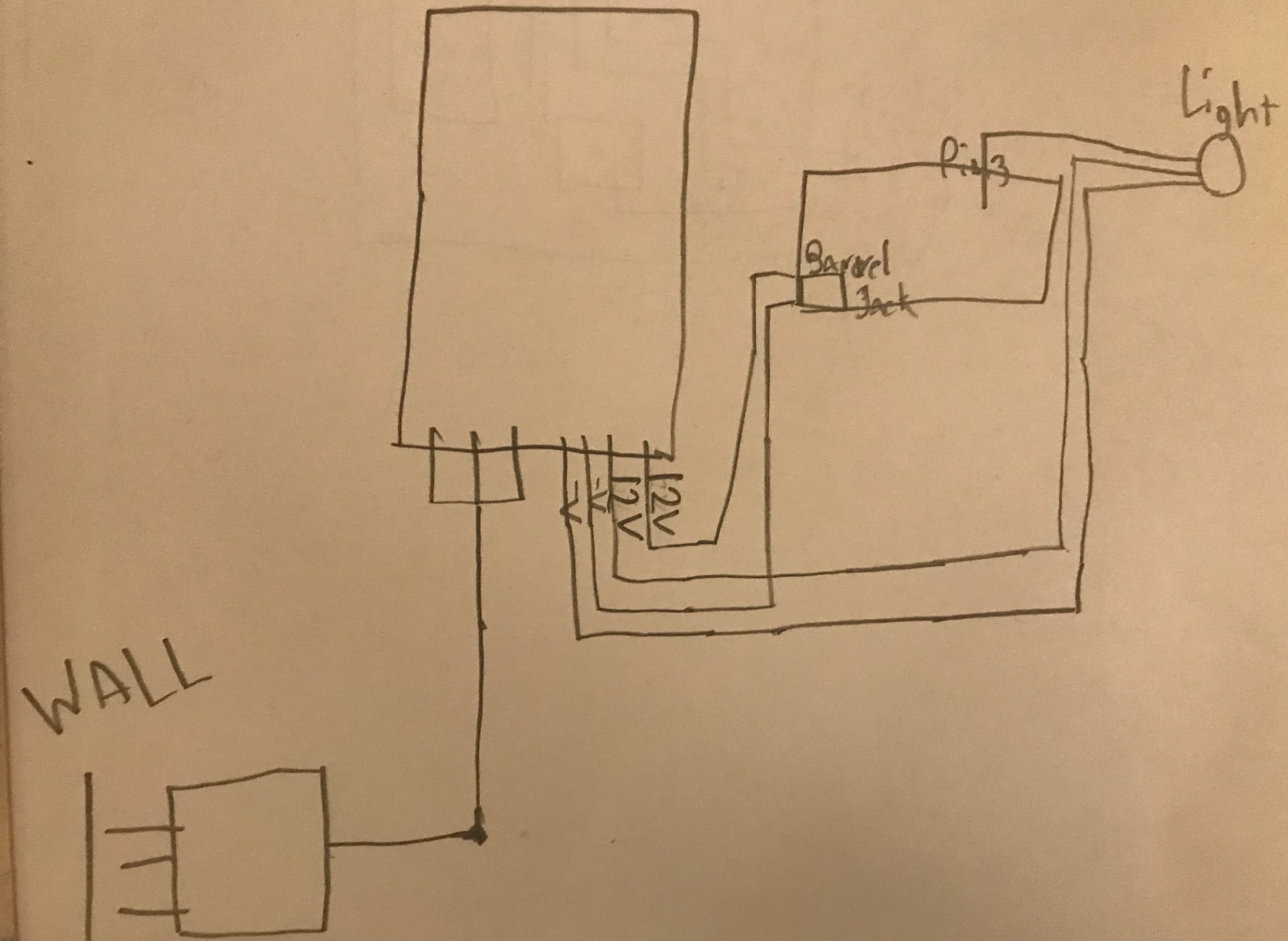
Thank you to everyone for replying! I drew the schematic out on paper. This is what believe I need to do. If I missed anything, please tell me!
@Grumpy_Mike 's advice from reply #8
And mine from #9!
Looking good. clear schematic.
So 3 things i see
I read that and then i wanted to reply, and then had to look again for it, but i found it. So what is relevant is how far apart things are going to be. If the lights are outside, and looking at the transformer, i would say that it will be put inside somewhere, or you will need a waterproof box to put it in.
Where are you going to put the Arduino ? Again the same issue of course, though a box for that is not to hard to come by, and there are big advantages to having it closer to the led string.
So regardless you will need cable of a fairly decent cable if you are going to run it outside, it should be insulated. Depending a little on the distance it will need to be fairly thick as well. As stated before voltagedrop is an X amount per meter, and the thicker the cable, the less the drop. I tend to use speaker cable because it is fairly cheap and readily available in thick gauges, but something double insulated like mains power lead could also be ok and may even be better. The distance it covers is relevant, and also the amount of leds is relevant. Standard 3 strand tri-colored cable comes in AWG 22, which in many cases is going to be to thin.
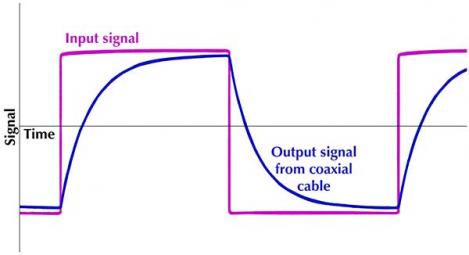
Now about the data cable. Ideally this is really short. The main issue with a high speed data signal (800 KHz is pretty quick) transfer is that all cables have. This image shows what happens to a data signal as a result of that.
Calculating capacitance is complex, but it is simple to understand. Capacitance is a 'physics effect' that takes place at the surface of metal when it is electrically charged. The cable starts to act like a (small) capacitor, and basically, the more surface, the more capacitance. So the longer the cable, the more capacitance, and also the thicker the cable, the more capacitance, and here it is the exact opposite of voltagedrop.
There are ways to counteract capacitance, but if you can manage to put your arduino close to the led string, you don't have to. With AWG 22 you can probably cover about 5 meters (and maybe more) And with a thinner cable even more, but a thin cable is fragile. And now the current limiting resistor on the data line me also be counter productive, so these are the considerations.
It may be practical to have the arduino indoor, so you don't need to waterproof it, and it is easy to upload a new sketch, but have it close to the string simplifies things as well. Choices....
About the waterproofing. The string itself is waterproof enough (probably IP67 or something), but the connecting plugs that come with it aren't. You can solder the whole thing together and use shrink-tube for isolation (and tape, found out where the cat took the roll of tape... ) but that might not be so practical when you install, put up, take down and stuff. Mind you most defects in installation are caused by the repeated putting up and taking down of deco regardless, but if it is all one thing that doesn't help.
There are (near) waterproof 3-pin plugs available and it is definitely handy to be able to easily connect extra power in between strings (of 50 leds) . You can also just try and make the non-waterproof plugs more water-resistant by using cling-wrap. I was hesitant to with this advice, but in truth. It is a 12v (or 5v) DC system, and water itself does not conduct much DC current (AC is a different matter !!). It is the ions in the water that does. In practice moisture does not cause much problems, but if you hang it in the rain for extended period of time, corrosion may cause issues. The more waterproof the better !! (of course, but also more expensive)
So as a final suggestion. If you use 12v string, you could power the string from the halfway point (or between say the first 50 leds and the last 100 leds, you don't have to cut one of the strings), reducing the voltage-drop to the last led. And.. power the arduino from the starting point of the first string. It will consume about the same amount of power as 1 Pixel at full brightness and that the voltage is a little less than 12v on the barrel jack is really not a problem (in fact it is better to power it with 9v than with 12v. 7v is the minimum requirement)
Of course the Arduino really should be housed near waterproof.
Oh yes, well for a 13 yr old you are sure asking the right questions ! Be careful with mains power please. And also with 12v (or 5v) power. Although not nearly as dangerous as mains, a power supply can provide the current it is rated for and a short can cause all of the current to flow through a cable, which may get really hot. These power supplies are not fused and a short will stop the ledstring from working but the power supply will probably not shut down by itself. Usually it is not an issue, if it is working it does not have a short, but i always test with a multimeter before i turn the power on. (the first time.. if it's fine it's fine i switch it on and off there after)