LOL.
Live long enough and you will have been blessed to receive tens of thousands of compiler errors.
a7
LOL.
Live long enough and you will have been blessed to receive tens of thousands of compiler errors.
a7
![]()
ok so
like this
#include <Adafruit_NeoPixel.h>
#include <HCSR04.h>

#define PIN        6 // Which pin on the Arduino is connected to the NeoPixels?

#define NUMPIXELS 29 // How many NeoPixels are attached to the Arduino?

Adafruit_NeoPixel pixels(NUMPIXELS, PIN, NEO_GRB + NEO_KHZ800);

UltraSonicDistanceSensor distanceSensor(9, 10);  // Initialize sensor that uses digital pins 9 and 10.


int current_Last_LED=0;

void setup()
{
 pixels.begin();

  pixels.setPixelColor(1, 0, 0, 255);    // blue
  pixels.setPixelColor(2, 0, 255, 0);    // green
  pixels.setPixelColor(3, 255, 0, 0);    // red

  pixels.show();
  delay (1000);
}

void loop()
{

}
that, yes.
Since you have a handy constant you can do the last pixel trick by adding a fourth to turn on, viz:
pixels.setPixelColor(NUMPIXELS - 1, 255, 255, 255); // white
Now all four pixels are full bright, you might go blind looking at them. Just use a smaller number than 255 everywhere, like 77, which will still look red, green, blur and white, but not be so dazzling.
If the simple sketch doesn't work, or makes odd colors, it makes no sense to worry about what your final objective is.
Divide and conquer.
It matters not, but you can strip all references and code for the ultrasound sensor, and tuck this test sketch away in your clip file.
a7
yay
thanks will try this and share results.
in an aim to achieve the final result.
well..
uploaded this.
#include <Adafruit_NeoPixel.h>
#include <HCSR04.h>

#define PIN        6 // Which pin on the Arduino is connected to the NeoPixels?

#define NUMPIXELS 29 // How many NeoPixels are attached to the Arduino?

Adafruit_NeoPixel pixels(NUMPIXELS, PIN, NEO_GRB + NEO_KHZ800);

UltraSonicDistanceSensor distanceSensor(9, 10);  // Initialize sensor that uses digital pins 9 and 10.


int current_Last_LED=0;

void setup()
{
 pixels.begin();

  pixels.setPixelColor(1, 0, 0, 255);    // blue
  pixels.setPixelColor(2, 0, 255, 0);    // green
  pixels.setPixelColor(3, 255, 0, 0);    // red

  pixels.show();
  delay (1000);
}

void loop()
{

}
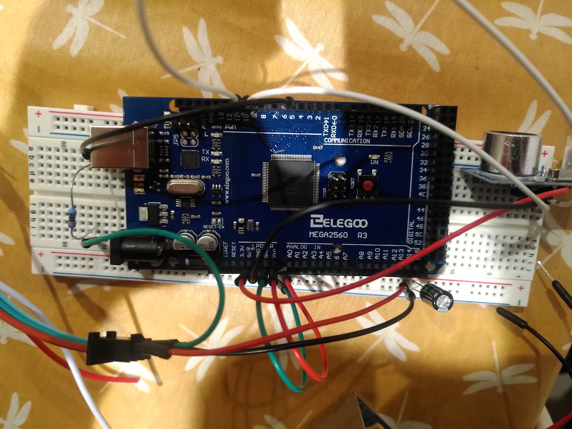
Nothing. no lights. nothing.
I took a picture of the setup incase something is wrong there.
its a bit tricky to see but it is as the diagram above shows.
if i just plug the + and GRD from the strip into the power supply and no DATA, should it come on? Im trying to check the strip still works.
ok so actually i must have had something wrong. Just re did it and it works fine.
the sensor is however doing nothing right now.
but i have 3 lights B/G/R.
so thats ok.
how do i get the sensor in there though?
Or whats next?
Many thanks
is there a code to test the sensor is working?
As perhaps you have realized with your success, there is no simple way to test a strip. The pixels only react to the receipt of a properly formed data stream, and the easiest way to send ione is with a small sketch.
You also may want to try to write a very small sketch that turns off all the LEDs on the strip.
I have one I keep open when I work with smart LEDs, just in case a code error causes the strip to start blinding me and any cats that happen to be in the lab… I just upload the "turn off 300 pixel" sketch and go to looking for what caused the excitement. You can always address more LEDs than you have physically. The Arduino can't even tell if any are attached, let alone that you only have 29 and not 129.
I'm in transit, but yes. There may be an example sketch already in the IDE. Better libraries bring in examlpes to show themselves off and sometimes as the best (only) real documentation of how to use them. These are found in Fikes/Examples. There might be one that just reads and reports using the serial monitor.
I'll check in later to see if you've fixed yourself up with a test for the device to be added.
Obvsly once you have a working strip one sketch and a working sensor the second sketch, "marrying" them should get you on the air with something that shoukd be fairly easy and probably a certain kind of fun to play with.
L8R
a7
Google is my friend!
#include <HCSR04.h>

byte triggerPin = 21;
byte echoPin = 12;

void setup () {
  Serial.begin(9600);
  HCSR04.begin(triggerPin, echoPin);
}

void loop () {
  double* distances = HCSR04.measureDistanceCm();

  Serial.print("1: ");
  Serial.print(distances[0]);
  Serial.println(" cm");

  Serial.println("---");
  delay(250);
}
You may need to adjust this, please read the sketch like you know what you are doing and see if.
a7
Hello again.
It was something to do with the way I have wired it together.
So it now works.
However it's ok for the first 2meters ish and then it jumps all over the place, I suppose a better sensor or even a different sensor type would improve this.
If I walk up and down it sort of stops at around 2 meters, but if I put a slightly reflective box down I can get all the 5 meter strip lit up and a stable signal, still a bit dogu when I move the box and it has to be Justin right place to stabilize the signal.
So I am kind of happy but not sure how to improve the sensor and I'm going to have to use another code when I get another sensor.
I have video but can't upload it.
Sorta kinda works. I've always wondered how well these sensors work after a long enough ago bad experience with some relatively more expensive units. They did not end up being any part the solution to the problem at hand. It did mean we wasted time and someone's money, however.
ultrasonic sensor best practices
and poke around for ideas.
This
has some good information, and shows how you could code for the sensor directly without the use of a library. That would open the door for tinkering with the pulse length of the burst and so forth.
But it does seem that they are better suited for some things than others.
It's not clear you don't have other issues, but this is down to, it seems, the quality of the sensor and your exact deployment circumstances.
Oh, say you did an experiment with just the sensor printing the raw return values.
a7
I would like to send you the videos.
I will have a look and see how I can do that.
It does seem clear that is something to do with the sensor as using a box instead of my legs the signal seems to work much better and the sensor therefore works much better.
Would it be terrible to ask for an email address.
Otherwise i will see if i can edit the video for wep use and see if i can upload it asap.
Many thanks
again.
I am looking now at using the LiDAR lunar to do the job.
I have no idea about quite how I am going to do it yet but I have until the 6th of Oct when it arrives to do some research about it.
If I can get it to send and receive data on the IC2 pins then maybe I can get it to trigger the lights on the strip with the adafruit code I am already using.
This is where things get really complicated as I can't find a video demonstration online so I can't use something someone has already created.
Fingers crossed I guess.![]()
Any advice would be greatly appreciated.
Just keep thinking of the two things the sketch does as separate.
The sensor and some maths gives you a number.
The number, no matter where it comes from, turns on some pixels.
This
shows simple enough code for how to get the number. I have no experience using any sensor like that, nor any idea if it works any better.
a7
Yes I have read that already.
I'm going to try and use the adafruit code from before and mix it with the LiDAR code once I have established a return value and I can see it's working. Hopefully there will be some workable code then and finally hopefully the results will be better.
hello
so finally got the lidar and have been having some goes.
this code is uploading, so thats good.
#include <Adafruit_NeoPixel.h>


#include <TFMPlus.h>  // Include TFMini Plus Library v1.5.0

 #define PIN        6 // Which pin on the Arduino is connected to the NeoPixels?

#define NUMPIXELS 50 // How many NeoPixels are attached to the Arduino?

Adafruit_NeoPixel pixels(NUMPIXELS, PIN, NEO_GRB + NEO_KHZ800);

TFMPlus tfmP;         // Create a TFMini Plus object

int16_t tfDist = 0;    // Distance to object in centimeters

void setup()
{

 pixels.begin();

}

// Initialize variables


// Use the 'getData' function to pass back device data.
void loop()
{

 pixels.clear();                               // Set all pixel colors to 'off'
  tfDist=tfmP.getData( tfDist);


  for(int16_t i=0; i<tfDist; i++)                      // For each pixel in strip...
  {
    pixels.setPixelColor(i, 0,0,255);
  }

  pixels.show();                                  // Send the updated pixel colors to the hardware.

}
The source code I managed to reduce to basically give me distance readings on the serial monitor.
/* File Name: TFMP_example.ino
 * Developer: Bud Ryerson
 * Inception: 29JAN2019
 * Last work: 10SEP2021

 * Description: Arduino sketch to test the Benewake TFMini Plus
 * time-of-flight Lidar ranging sensor using the TFMPlus Library.

 * Default settings for the TFMini Plus are a 115200 serial baud rate
 * and a 100Hz measurement frame rate. The device will begin returning
 * measurement data right away:
 *   Distance in centimeters,
 *   Signal strength in arbitrary units,
 *   and an encoded number for Temperature in degrees centigrade.

 * Use the 'sendCommand()' to send commands and return a status code.
 * Commands are selected from the library's list of defined commands.
 * Parameters can be entered directly (115200, 250, etc) but for
 * safety, they should be chosen from the library's defined lists.
 */

#include <TFMPlus.h>  // Include TFMini Plus Library v1.5.0
TFMPlus tfmP;         // Create a TFMini Plus object

#include "printf.h"   // Modified to support Intel based Arduino
                      // devices such as the Galileo. Download from:
                      // https://github.com/spaniakos/AES/blob/master/printf.h

// The Software Serial library is an alternative for devices that
// have only one hardware serial port. Delete the comment slashes
// on lines 37 and 38 to invoke the library, and be sure to choose
// the correct RX and TX pins: pins 10 and 11 in this example. Then
// in the 'setup' section, change the name of the hardware 'Serial2'
// port to match the name of your software serial port, such as:
// 'mySerial.begin(115200); etc.

//#include <SoftwareSerial.h>
//SoftwareSerial mySerial( 10, 11);

void setup()
{
    Serial.begin( 115200);   // Intialize terminal serial port
    delay(20);               // Give port time to initalize
    printf_begin();          // Initialize printf.
    printf("\r\nTFMPlus Library Example - 10SEP2021\r\n");  // say 'hello'

    Serial2.begin( 115200);  // Initialize TFMPLus device serial port.
    delay(20);               // Give port time to initalize
    tfmP.begin( &Serial2);   // Initialize device library object and...


}

// Initialize variables
int16_t tfDist = 0;    // Distance to object in centimeters

// Use the 'getData' function to pass back device data.
void loop()
{
    delay(50);   // Loop delay to match the 20Hz data frame rate

    if( tfmP.getData( tfDist)) // Get data from the device.
    {
      printf( "Dist:%04icm ", tfDist);   // display distance,
      printf( "\r\n");                   // end-of-line.
    }

}
the problem I think from there is that the lidar is sending to TX1 and RX2.
now my knowledge is limited so pardon me but when using the USsensor it was all digital pins no TX/RX and I wonder if this is an issue.
also the UScode shows:
UltraSonicDistanceSensor distanceSensor(9, 10);  // Initialize sensor that uses digital pins 9 and 10.

on line ten this initializes the sensor.
my above code i have used
TFMPlus tfmP; // Create a TFMini Plus object
but that creates the object rather than initializing it.
not sure.
Any ideas
OK so with some help I have this working.
CODE looks like this.
#include <Wire.h>
#include <Adafruit_NeoPixel.h>

// #include <HCSR04.h> replaced by...
#include <TFLI2C.h>

#define PIN        6 // Which pin on the Arduino is connected to the NeoPixels?
#define NUMPIXELS 20 // How many NeoPixels are attached to the Arduino?

Adafruit_NeoPixel pixels(NUMPIXELS, PIN, NEO_GRB + NEO_KHZ800);

// UltraSonicDistanceSensor distanceSensor(9, 10);  // Initialize sensor that uses digital pins 9 and 10.
// replaced by...
TFLI2C tflI2C;

int current_Last_LED = 0 ;
int16_t  tfAddr = TFL_DEF_ADR;    // default I2C address
int16_t  tfDist;   // distance in centimeters

void setup()
{
  Serial.begin( 115200);  // Initalize serial port
  Wire.begin();           // Initalize Wire library
  pixels.begin();
}

void loop()
{
  pixels.clear();
  if( tflI2C.getData( tfDist, tfAddr))                              // Set all pixel colors to 'off'
  current_Last_LED=(tfDist)*0.8;
  //replaced by...
  //tfDist=tflI2C.getData( tfDist, tfAddr);

  if( current_Last_LED <=NUMPIXELS)   // If reading is out of range, then...
  {
	  for(int i=0; i<current_Last_LED; i++) // For each pixel in strip...
	  {
		pixels.setPixelColor(i, 25,25,00);
	  }
	  pixels.show();	  // Send the updated pixel colors to the hardware.
  }
  else pixels.clear();    // Otherwise clear the display
}
Only thing I am having issue with now is that sometimes when I move out of range the LEDS stay on, so it's working but its a bit unreliable.
Any ideas.
I will post a video soon.
Print the value of the sensor to see why. The code does what you tell it, so this is a matter of logic first. Then maybe the sensor is doing something wonky.
You flying blind otherwise.
a7