So I had a perfectly functioning strip of 42 LEDs. I wanted to create two duplicates from the same controller, so I spliced into the data, tied the grounds together, and used a separate power supply. It worked great! I had 3 strips behaving the same.
Then I wanted to do the same thing with a strip of 62 lights. I repeated the process, and ALMOST everything worked perfectly. The two new strips are perfect…. But the original strip is suddenly flickering and not really following the program. I remade the wiring harness thinking I must have made a bad connection, but still have the same issue. Weird! The run for the old strip is the same, the new strips run four to eight feet away, and they’re the ones that are fine. Obviously there is something I don’t understand. Thanks so much for any wisdom!
Oh man, you’re gonna hate me. I drew the thing, not on a computer. Here’s the pic. The right side is basically the same as the left. The top is the original wiring, everything underneath it is what I added. All that is working fine. It’s the very top part of the drawing, the original “from game to game” where something weird is happening.
I’m not at home now but I’ll post pics of the wiring when I get there. Thanks for even looking, Nice people. I’d think it was a power issue except that I didn’t borrow from the original power at all. When I disconnect my new harness and plug the old one back in, everything is fine again with the original strip. It seems like the data signal gets messed up when I plug in the new stuff, but only to the original strip. It is trying to follow the program but it is not doing it well and is constantly flickering.
Below is a project layout I did a while back.
Note the Yellow area.
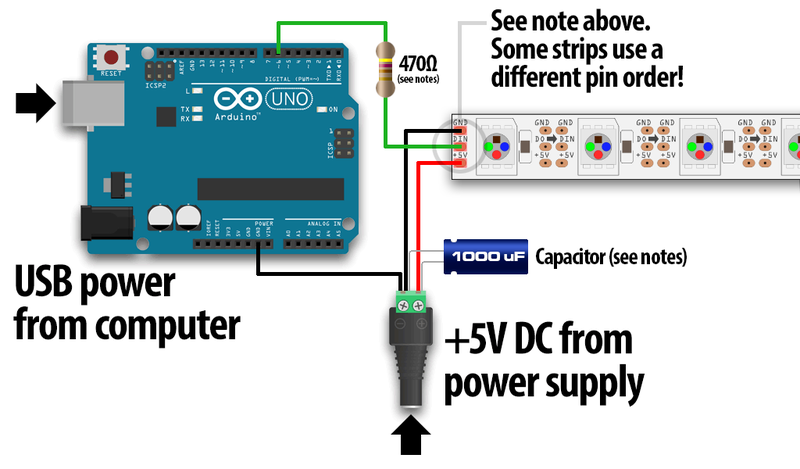
The Arduino pin 12 goes to 5 resistors then each resistor goes to a separate LED strip.
Infinitely better than Fritzing crap.
You do need a series resistor for the data lines- one per string. I would use 1K. The resistor is for impedance matching- especially when driving strings in parallel.
I call it ground now! I drew this before I started reading and errantly named it neutral on the plans. I’ll have to figure out where I can pick up resistors or order online, I haven’t found any electronics or decent hobby stores in the area yet.
This one probably looks weird because it’s a pinball machine and I’m just using the data line from its existing led strips. They were probably smart enough to put a resistor as you mention in line on the way to the strips and maybe I’m hijacking the signal from before the line gets to it. I wonder if I can find schematics to tell me.
Voltages at each strip are reading 4.9 to 5.05 consistent, just for fun I checked data line voltages and they’re all sitting at 2.3. The wiring block I’m using is really ugly and I intend to clean it up when everything is working well. Anyway, I’ll show pics in a second. The colors at the Molex connectors aren’t by the book because I was using what I had around, but the game’s power is passed through, and I tapped into each side’s data and ground in the Molex connector as I pinned them.
Your are most likely suffering from the 'capacitance' of the data cable. Capacitance is a phenomena that is caused by electrons piling up the surface of metal wire, which makes the cable act as a capacitor. This in effect causes the data signal to change slightly from a square wave into something which, depending on the amount, resembles a saw wave. To be exact the wave starts to look a bit like the teeth on the chain of a chain saw. ws281x chips are edge triggered and very timing sensitive and can not tolerate a lot of capacitance on the data line.
As with capacitors, capacitance of the cable is additive when the cables are parallel (as they are with you) So if you tell me how long your data line is, all added together !
You want to lowest capacitance possible, so you want the thinnest cable, preferably solid, not multi-strand, because this would mean less surface. That your first strip starts to have issues is coincidence, the other strips must also be close to having problems.
The easiest and most effective solution is to add a TLL chip in your circuit, where you connect each strip to it's own output. I usually use a 74HCT04 where i make the signal pass through 2 NOT-gates, and split it in between, so i can get 5 output out of the 6 gates that are on the IC.
These are great ideas, thank you! It’s above my knowledge level but with these thoughts and some reading perhaps I can figure out how to make this work. Really appreciate it
Exactly, you have produced some very informative images and circuit diagram and construction wise the terminal strip for the LED strips is great.
Bringing all power leads to one point and securely, has made sure your connections are stable, which on many projects we find can be the major problem to circuit malfunctions.
As a first time poster @djpletcher well done in providing the needed info to help your project.
If this was with a DVM, then it's meaningless. You can only look at data with an oscilloscope or logic analyzer. (I had to add the logic analyzer even though only one in a hundred experimenters would have one, but if I didn't, someone would jump on me with "..and a logic analyzer").
Not a power issue?? Prove it. Remove any one string from the circuit. If the flicker stops, then you do have a power issue.
I don't put strips' data lines in parallel, I just drive them with another data pin on the processor board. Yes, it's more coding but it gives you the flexibility to make each strip unique, or alike.