I have a weird problem I can't figure out.
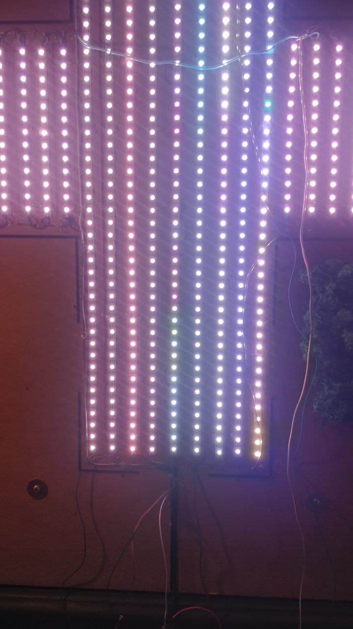
I have an LED installation with a lot of strips (WS2812B). Because of the huge power consumption I installed two power supplies.
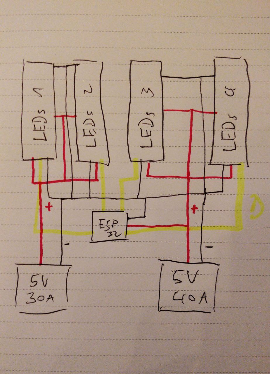
One is 5v 30a, the other 5v 40a.
Ground IS connected between both. Plus is NOT connected.
Data comes from an ESP32. I tried different codes - FastLED and WLED, both have the same Issue.
The issue:
When I Connect only one power supply the connected LEDs work as intended
Hi,
Can you please post a copy of your circuit, in CAD or a picture of a hand drawn circuit in jpg, png?
Hand drawn and photographed is perfectly acceptable.
Please include ALL hardware, component names and pin labels.
Make sure you show how your supplies are connected.
Can you please post link to specs/data of the power supply.
If you are connecting both supplies in parallel, that could be your problem.
Have you split the LEDs up into to separate supply rails, with common gnd?
Can you post image(s) of your wiring of the LEDs, you should have bypassing wires to help provide current along to the end of your LED strips.
As written I'm not connecting them in parallel, ground IS connected, 5v is separated between both supplies.
I have an ESP32 and 4 clusters of LEDs. Each with its own output on the ESP.
2 Clusters are driven by the 30a power supply, the other 2 by the 40a.
ESP32 is connected to the 40a (but the problem is the same when its connected to the other one)
I have several Power injections along the length of the strip.
By the way. I tried to connect "LEDs 3" to different outputs on the ESP32. Also changed the code to only display some of the LEDs. Still the same effect (only with less LEDs). Still on "LEDs 3". It has to be something in the wiring or power distribution. Strange thing is there is no Problem on "LEDs4" which is in the exact same power wiring.
Have you got the series resistor in each of the signal wires to each LED strip?
Note the suggestion;
Before connecting NeoPixels to any large power source (DC “wall wart” or even a large battery), add a capacitor (500–1000 µF at 6.3V or higher) across the + and – terminals as shown above. The capacitor buffers sudden changes in the current drawn by the strip.
Clearly, when you energize the second power supply more current flows, overall. Clearly, when you then reduce intensity, less current flows. I have a strong suspicion you have a weak interconnection, or too many LEDs on one of the supplies, but we have yet to see a picture of your assembly, nor have we seen your code, either of which would have helped give a sense of the magnitude. Certainly, with 70A of 5V current available, there'd better be some beefy wiring involved.
Please provide a bit more detail.
Thanks
i'm still suspicious, since that reference between supply grounds should only ever see signal return currents (at most a few mA), unless you've crossed something up, but whatever, if you're happy, we move on.
How can I test for a crossed connection or a wrong wiring?
I tested everything for continuity with the multimeter. And there is current flow in all the grounds and in both the 5v circles separately.
Well, you could simply disconnect the four power supply leads, then check for continuity between them. Should be infinity between the + leads, 0 or close to it between the - leads. Then remove the wire you say connects the two, and you should have infinity between the two - leads. If not, investigate. That's what I'd do, anyway, for starters.
Thanks for asking. Actually not. Everything is good. Everything around 0.1 Ohm. 0.3 was the maximum I found. But that could be due to being on the other end of the line.
I will change my injection cable to something bigger. That one is the last thing I can change. Otherwise everything should be good to go.