WT32-ETH01 ethernet stop working after adding some pinMode function

Hi guys,
I have created a sketch that uses the ethernet module from the ESP.
Everything is working fine until I've added the pinMode function, which seems to be breaking the ethernet module from working.

when I remove the pinMode part it's back to work as expected,
The pin I have chooses to use are

#define GREENLED 19 // POWER LED
#define YELLOWLED 18 // SCALE LED
#define BLUELED 16 // ETHERNET LED

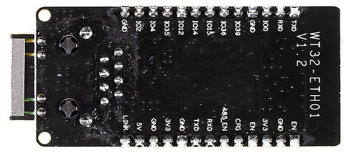
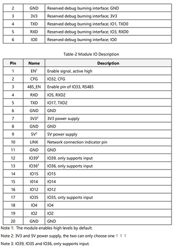
According to WT32-ETH01 sheets those pin are not in used at all:

BTW: I didn't even connect the LED to the esp.

This is my code:

#include <Arduino.h>
//#include <WiFi.h>
#include <WebSocketsClient.h>
#include "StompClient.h"
#include <ArduinoJson.h>
#include <SoftwareSerial.h>
#include <WebServer_WT32_ETH01.h>

#define DEBUG_ETHERNET_WEBSERVER_PORT       Serial
#define GREENLED 19 // POWER LED
#define YELLOWLED 18 // SCALE LED
#define BLUELED 16 // ETHERNET LED

// Debug Level from 0 to 4
#define _ETHERNET_WEBSERVER_LOGLEVEL_       0


/** 
* Ethernet settings
*/

// Select the IP address according to your local network
IPAddress myIP(192, 168, 1, 232);
IPAddress myGW(192, 168, 1, 1);
IPAddress mySN(255, 255, 255, 0);

// Google DNS Server IP
IPAddress myDNS(8, 8, 8, 8);


/**
* Stomp server settings
**/
bool useWSS                       = false;
const char* ws_host               = "192.168.1.50";
const int ws_port                 = 8080;
const char* ws_baseurl            = "/stomp/"; // don't forget leading and trailing "/" !!!
char* deviceId = "A1B2C3D4";
char* subscribeDestination = "/subscriber/";
char* sendDestination = "/api/v1/sendmessage/";


// VARIABLES
String inString = "";
float weight;
WebSocketsClient webSocket;
SoftwareSerial myPort;
Stomp::StompClient stomper(webSocket, ws_host, ws_port, ws_baseurl, true);
boolean getScaleSample = false;

// Once the Stomp connection has been made, subscribe to a topic
void subscribe(Stomp::StompCommand cmd) {
  Serial.println("Connected to STOMP broker");
  stomper.subscribe(concatinateString(subscribeDestination, deviceId), Stomp::CLIENT, handleResponse);
  
  sendMessage(concatinateString(deviceId," is logged!"));
}

void error(const Stomp::StompCommand cmd) {
  Serial.println("ERROR: " + cmd.body);
}

Stomp::Stomp_Ack_t handleResponse(const Stomp::StompCommand cmd) {
  //**
  
  return Stomp::CONTINUE;
}

void sendMessage(String message) {
  stomper.sendMessage(concatinateString(sendDestination, deviceId), message);
}

char* concatinateString(char* str1, char* str2) {
  char *buffer = (char*)malloc(strlen(str1) + strlen(str2)+1);
  sprintf(buffer, "%s%s", str1, str2);

  return buffer;
}

void setup() {
  Serial.begin(115200);

  Serial.print("\nStarting BasicHttpClient on " + String(ARDUINO_BOARD));
  Serial.println(" with " + String(SHIELD_TYPE));
  Serial.println(WEBSERVER_WT32_ETH01_VERSION);

  // To be called before ETH.begin()
  WT32_ETH01_onEvent();
  ETH.begin(ETH_PHY_ADDR, ETH_PHY_POWER);
  ETH.config(myIP, myGW, mySN, myDNS);

  WT32_ETH01_waitForConnect();
  Serial.print(F("HTTP EthernetWebServer is @ IP : ")); 
  Serial.println(ETH.localIP()); 


  pinMode(BLUELED, OUTPUT);
  pinMode(GREENLED, OUTPUT);
  pinMode(YELLOWLED, OUTPUT);

  digitalWrite(GREENLED, LOW);
  digitalWrite(BLUELED, LOW);
  digitalWrite(YELLOWLED, LOW);


  myPort.begin(9600, SWSERIAL_8N1, MYPORT_RX, MYPORT_TX, false);
  if (!myPort) { // If the object did not initialize, then its configuration is invalid
    Serial.println("Invalid SoftwareSerial pin configuration, check config"); 
    while (1) { // Don't continue with invalid configuration
      delay (1000);
    }
  } 

  // Start the StompClient
  stomper.onConnect(subscribe);
  stomper.onError(error);

  if (useWSS) {
    stomper.beginSSL();
  } else {
    stomper.begin();
  }
}

void loop() {
  webSocket.loop();
  /*if (WT32_ETH01_isConnected()){   
    if(digitalRead(BLUELED != LOW)){
      digitalWrite(BLUELED, LOW);
    }
  }else{
    if(digitalRead(BLUELED != HIGH)){
      digitalWrite(BLUELED, HIGH);
    }
  }*/
  

  if(myPort.available() > 0){
    int inChar = myPort.read();
    //digitalWrite(BLUELED, inChar);
    if(inChar != '\n'){
      inString += (char)inChar;
    }else{
      inString.remove(0,2);
      weight = inString.toFloat();
      if(getScaleSample){
        sendMessage((String) weight);
        getScaleSample = false;
      }
      inString = "";
    }
  }

}

Does anyone have any idea why the pinMode function breaks it?

Thanks!
Why use software serial when a ESP32 has 3 hardware ports you can use?

If you really NEED software serial use ESPSoftwareSerial.

did you try one at a time?


pinMode(BLUELED, OUTPUT);
//  pinMode(GREENLED, OUTPUT);
 // pinMode(YELLOWLED, OUTPUT);

Have you considered putting the ethernet code on one core and your other code on another core?

I will try with hardware ports, thanks.

Yes, I have tried with all three pins one at a time, and the esp acts the same.

What do you mean by putting them on a different core?
I need them to work together

The ESP32 has 2 cores Code can be put on one core and code can be put on the other core to run. There are thingies to allow cross core communications.

Normally for an ESP32 WiFi and BLE are put onto core0 and Arduino code is put onto core1.

Oh, is your ESP a 8266? In that case it only has one core.

Pins 16, 18 and 19 do not seem to be labelled on the board


Are you confusing the pin numbers of the ESP32 module itself and the pin numbers as they are mapped and labelled on the board

Hi, @UKHeliBob
According to the sheets pins
16 is mapped to IO12
18 is mapped to IO4
19 is mapped to IO2
image

this is not the right way to use them?

In the Arduino programming environment it is normal to use the pin numbers as marked on the board rather than the pin numbers of the module

Which board pins are you intending to use for the LEDs ?

Try a simple sketch to blink the LEDs on the pins of your choice

1 Like

Just to be more clear, you are saying that I need to use the "Pin Name" instead of "Pin Number"?
Let's say I want to use the pin bordered with red from the below picture:
image

so the code should be like that?

  pinMode("IO12", OUTPUT);
  pinMode("IO4", OUTPUT);
  pinMode("IO2", OUTPUT);

For an ESP32 I tend to use ESPRESSIF's pin notation of GPIO_NUM_x where x = GPIO pin number.

pinMode( GPIO_NUM_123456789, OUTPUT);

I have tried that with the idea that UKHeliBob suggested and it seems to be the LED is not turning on.

I have taken Blink example from the IDE and modified it a bit:

void setup() {
  Serial.begin(115200);
  pinMode(GPIO_NUM_19, OUTPUT);

  Serial.println("Started.");
}

void loop() {
  digitalWrite(GPIO_NUM_19, HIGH);   // turn the LED on (HIGH is the voltage level)
  delay(1000);   // wait for a second                 
  Serial.print("Current read from GPIO_NUM_19: ");
  Serial.println(digitalRead(GPIO_NUM_19));   
  digitalWrite(GPIO_NUM_19, LOW);    // turn the LED off by making the voltage LOW
  delay(1000);  
  Serial.print("Current read from GPIO_NUM_19: ");
  Serial.println(digitalRead(GPIO_NUM_19));                   // wait for a second
}

This is the response:

Current read from GPIO_NUM_19: 0
Current read from GPIO_NUM_19: 1
Current read from GPIO_NUM_19: 0
Current read from GPIO_NUM_19: 1
Current read from GPIO_NUM_19: 0
Current read from GPIO_NUM_19: 1
Current read from GPIO_NUM_19: 0
Current read from GPIO_NUM_19: 1
Current read from GPIO_NUM_19: 0
Current read from GPIO_NUM_19: 1
Current read from GPIO_NUM_19: 0
Current read from GPIO_NUM_19: 1
And more...

The LED is plugged into IO2 as mentioned inside the sheets:
image

It seems to be that the pin's digital state changed, but the LED is not turned ON/OFF at all(remain off).
Could it be that the pin list is incorrect?

Are you sure that you have the LED connected the right way round, that it lights if connected between 3.3V and GND and that you have the correct value of current limiting resistor in series with it ?

Yes if I bridge it with 3.3v the LED is turning ON.
The resistor I am using is 200ohm in between 3.3V to the VIN of the LED

does this blink LED's?

#include "esp_system.h"
#include "freertos/FreeRTOS.h" //freeRTOS items to be used
#include "freertos/task.h"

void setup() 
{
  Serial.begin(115200);
  //
  gpio_config_t io_cfg = {}; // initialize the gpio configuration structure
  io_cfg.mode = GPIO_MODE_OUTPUT;
  io_cfg.pin_bit_mask = ( (1ULL << GPIO_NUM_2) | (1ULL << GPIO_NUM_19) ); //bit mask of the pins to set, assign gpio number to be configured
  gpio_config(&io_cfg);
  gpio_set_level( GPIO_NUM_19, LOW );
  gpio_set_level( GPIO_NUM_2,LOW );
  //
  
  xTaskCreatePinnedToCore( Blink19, "Blink19", 10000, NULL, 3, NULL, 1 ); //assigned to core1
  xTaskCreatePinnedToCore( Blink2, "Blink2", 10000, NULL, 3, NULL, 0 ); //assigned to core0
  Serial.println("Started.");
}

void Blink19( void * pvParameters )
{

for(;;)
{
  gpio_set_level( GPIO_NUM_19, HIGH );
  vTaskDelay( 1000 );
  gpio_set_level( GPIO_NUM_19, LOW );
  vTaskDelay( 1000 );
}
  
}
////
void Blink2( void * pvParameters )
{

  for(;;)
  {
    gpio_set_level( GPIO_NUM_2, HIGH );
    vTaskDelay ( 700 );
    gpio_set_level( GPIO_NUM_2, LOW );
    vTaskDelay( 500 );
  }
}
void loop() {}

?

Yes, it is turning on the LED, it's not possible to have them on the same core?

just change the core assignment of xTaskCreatePinnedToCore().

Enter the words "xtaskpinnedtocore" into the proper search engine to find out how.

I'd lower the ram use of each task from 10K to 2K. If you add more code to the tasks then you'll need to increase stack size.

I'm trying to get rid of the "Blink2" and for some reason the LED stop working,

//#include "esp_system.h"
//#include "freertos/FreeRTOS.h" //freeRTOS items to be used
//#include "freertos/task.h"

void setup() 
{
  Serial.begin(115200);
  //
  gpio_config_t io_cfg = {}; // initialize the gpio configuration structure
  io_cfg.mode = GPIO_MODE_OUTPUT;
  io_cfg.pin_bit_mask = ( (1ULL << GPIO_NUM_19) ); //bit mask of the pins to set, assign gpio number to be configured
  gpio_config(&io_cfg);
  gpio_set_level( GPIO_NUM_19, LOW );
  //
  
  xTaskCreatePinnedToCore( Blink19, "Blink19", 10000, NULL, 3, NULL, 0 ); //assigned to core1
  Serial.println("Started.");
}

void Blink19( void * pvParameters )
{

for(;;)
{
  gpio_set_level( GPIO_NUM_19, HIGH );
  vTaskDelay( 1000 );
  gpio_set_level( GPIO_NUM_19, LOW );
  vTaskDelay( 1000 );
}
  
}

void loop() {}

There is a way to turn then ON/OFF without the core thing?

Sure just rewrite the code without using the core thing.

//#include "esp_system.h"
//#include "freertos/FreeRTOS.h" //freeRTOS items to be used
//#include "freertos/task.h"

void setup() 
{
  Serial.begin(115200);
  //
  gpio_config_t io_cfg = {}; // initialize the gpio configuration structure
  io_cfg.mode = GPIO_MODE_OUTPUT;
  io_cfg.pin_bit_mask = ( (1ULL << GPIO_NUM_19) ); //bit mask of the pins to set, assign gpio number to be configured
  gpio_config(&io_cfg);
  gpio_set_level( GPIO_NUM_19, LOW );
  //
  
  Serial.println("Started.");
}


void loop() 
{
  gpio_set_level( GPIO_NUM_19, HIGH );
  Delay( 1000 );
  gpio_set_level( GPIO_NUM_19, LOW );
  Delay( 1000 );
}

Hey,
I am checking your code and changed it a bit, and for some reason the LED is not turning ON/OFF
any suggestion?

#include "esp_system.h"
#include "freertos/FreeRTOS.h" //freeRTOS items to be used
#include "freertos/task.h"

void setup() 
{
  Serial.begin(115200);
  //
  gpio_config_t io_cfg = {}; // initialize the gpio configuration structure
  io_cfg.mode = GPIO_MODE_OUTPUT;
  io_cfg.pin_bit_mask = ( (1ULL << GPIO_NUM_19) ); //bit mask of the pins to set, assign gpio number to be configured
  gpio_config(&io_cfg);
  gpio_set_level( GPIO_NUM_19, LOW );
  //
  
  Serial.println("Started.");
}


void loop() 
{
  gpio_set_level( GPIO_NUM_19, HIGH );
  delay( 1000 );
  gpio_set_level( GPIO_NUM_19, LOW );
  delay( 1000 );
}

does this do a print out?


#include "esp_system.h"
#include "freertos/FreeRTOS.h" //freeRTOS items to be used
#include "freertos/task.h"

void setup() 
{
  Serial.begin(115200);
  //
  gpio_config_t io_cfg = {}; // initialize the gpio configuration structure
  io_cfg.mode = GPIO_MODE_OUTPUT;
  io_cfg.pin_bit_mask = ( (1ULL << GPIO_NUM_19) ); //bit mask of the pins to set, assign gpio number to be configured
  gpio_config(&io_cfg);
  gpio_set_level( GPIO_NUM_19, LOW );
  //
  
  Serial.println("Started.");
}


void loop() 
{
Serial.println("click");
  gpio_set_level( GPIO_NUM_19, HIGH );
  delay( 1000 );
Serial.println("clack"):
  gpio_set_level( GPIO_NUM_19, LOW );
  delay( 1000 );
}

If "click" and "clack" are being printed then your led is wired wonky.

it is printing click, clack. And I'm pretty sure the LED is plugged correctly.
If I give him 3.3v its turning on, and don't forget that the example with the core worked for me