It isn't my code to post. I have not spoken to my friend in months. I'll try and get together with him tonight and see if either he can post it, or give me permission to post it.
Hi polymorph,
Have you had any luck with the code for the x27.168 steppers?
I’m still looking at this - could this just be hard coded ( rather than build a library) ? Switching digital outputs with a delay between them as required - anyone tried this sort of thing ?
The arduino-IDE-included MotorVID28 library tells me: "This Library controls VID28 and equivalent steppermotors (X25, BKA30D-R5, VID29). It can control a stepper either using 6 steps mode or microsteps mode (24 steps) using PWM." Unfortunately it is inaccurate, at least for my X27 with the needle I have. I suspect the rapid accelerations at start/stop throw it off. It is not a strong stepper motor.
The SwitecX25 library at GitHub - clearwater/SwitecX25: Arduino library for Switec X25.168 and friends seems to include code to handle acceleration better and explicitly says: "The rate at which these miniature stepper motors can accelerate is dependent upon the inertia of the needle you are using. You may need to tune the acceleration tables in the library for your needle." As far as I can see, this library seems to work fine for me without tuning.
Edited to add: I'm using the three-pin connection hinted at in the first library above, straight on the Arduino GPIO pins, but with flyback diodes. The SwitecX25 library wants four pin numbers, I simply gave 9,10,10,11. Works like a charm.
The SwitecX25 library wants four pin numbers, I simply gave 9,10,10,11.
There is no obvious reason to use four, see state diagram below. Note that the middle two "pins" always have the same state. Perhaps four pins were intended to divide up the current flow. Thanks for the links!
// State  3 2 1 0   Value
// 0      1 0 0 1   0x9
// 1      0 0 0 1   0x1
// 2      0 1 1 1   0x7
// 3      0 1 1 0   0x6
// 4      1 1 1 0   0xE
// 5      1 0 0 0   0x8
I’ve just bought, off e-bay, the AX1201728SG quad drive chip for these motors , works well , cheap, and simple to use without any library . ( one pin for direction, one for “pulses” to generate the steps ( rising edge generates one micro step -15deg of the rotor ( which of course is geared down).
Needs a small delay between steps ( so the chip doesn’t think it’s noise?) , data sheet is out there too, from switec .
Motor runs pretty fast and very smooth.
That is awesome! It used to be that you could only get the specialized IC by buying huge quantities.
So let's make an open source PCB!
Hi All
You will not find a proper good working code to drive the switec x27 stepper motor on this site or just about anywheres on the internet. All the git hub libraries and codes that you will find none will work to drive the stepper motor properly the switec stepper motors and most if not all instrument stepper motors are bipolar steppers. they operate the same way any bipolar stepper motor does. The switec x 27 stepper motor can be driven directly from an atmega328 without any type of stepper driver or flyback diodes. I have been working with stepper motor instruments for 5 plus years no instruments that I have repaired. worked with or reverse engineered such as VDO, stack. new vintage, autometer. glow shift and a bunch of no name brands use drivers or diodes.If you want a properly working code for the switec stepper motor your best bet is to hire someone to write a good working code for you. There is the next problem I hired several experts to write my code for me. good luck on that one. The code I write myself worked better than the experts codes did. Yes they wrote me a code but I dont think they really understood how a stepper motor instrument was suppose to work.one finally refused to work with me, like it was my fault that his code did not work properly. Then I found the guy that I have now he writes the codes for me sends them to me I test them he makes some revisions and they are done. The latest code that I need he tests it on a test instrument that I sent him to make sure they work properly before sending them to me. as another member of this forum told me,you will not find anyone here that will help you.
Great forum lots on very intelligent people lots of good info, but nothing is free. Hire someone.
DAS
Just my uneducated ramblings
@DASbur: See reply #25.
Hi All
Been there done that all fine and good you can drive the stepper. But without some type of signal processor you have nothing. you cant measure an rpm or voltage signal with a stepper motor driver.
you need a processor to do that. eliminate the driver and drive the motor right off the atmega. just about every aftermarket gauge manufacturer does it this way. automotive instrument clusters do use a stepper motor driver but it is getting either a step direction or PWM from a BCM or PCM
DASBUR
I’m thinking of building a board for it , when I’ve time !
- one chip can drive 4 motors directly.
Hi, here's my take on the gauge stepper driver.
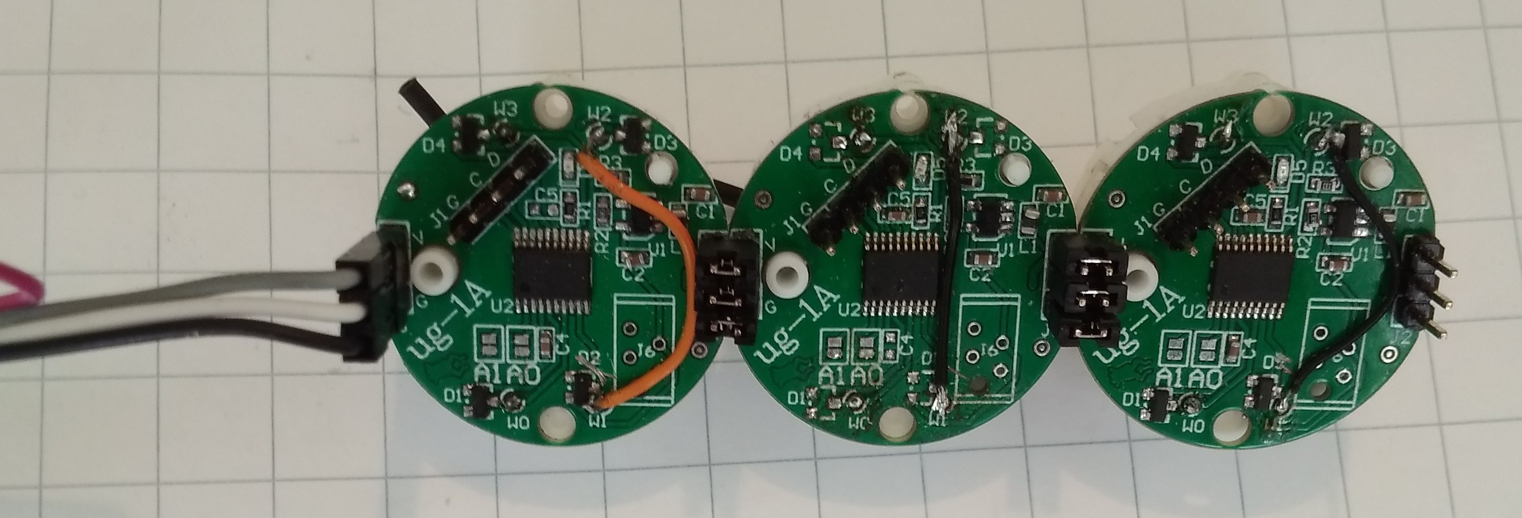
Each gauge has its own microcontroller/driver, daisy chained to up to 15. Controlled by just one Arduino's serial TX plus 0/5V power, each stepper is individually addressable. An ultra-simple protocol directs pointer movement to any position from 0 to 944. Ramps up and down, works like a charm.
Shown are three units daisy-chained with jumpers, normally the chain would be made with a 3-conductor strip. Forgive the blue wire...
-e

2 Likes
Why don't you give a little more detail?
detown:
Why don't you give a little more detail?
Sure. You can also ask specifics.
The micro is a STM32F030 in a TSSOP-20 package. Each of the four coil ends is driven by two output pins in parallel, push-pull. This gives abundant driving current. The usual two Back-EMF suppressing diodes are BAV199 in a dual package.
The daisy-chained supply can be anywhere from 3.7 to 16V, but the serial line must be limited to 3.6V which is the micro operating voltage. Incidentally, there's no need for a 5V supply: I found that the stepper works reliably from 2.3V up, so 3.6V is more than enough.
-e
1 Like
detown:
Why don't you give a little more detail?
The stepper is driven in “partial steps”, each advancing the pointer by 1/3 degree. The full pointer scale of 315 deg thus resolves to 945 “partial steps” Pointer positions are consequently numbered from 0 to 944. A movement command specifies the address of the target gauge in the daisy chain, an ‘M’ for “Move”, and the target position in decimal:
As an example, the command “3M477” directs the third gauge down the daisy chain to move its pointer to exactly mid-scale. Currently the only other available command is “Z” as in “2Z” which directs the second gauge pointer to the minimum (zero) physical stop at slow speed. This is typically used at power-up.
Addressing pointer positions uniformly from 0 to 944 means that a gauge has no inherent “knowledge” about the unit it is supposed to display. Together with the simple addressing scheme, this brings a few advantages: driver boards are all the same and interchangeable; Firmware need not be customized for each gauge. On the other hand, the controlling CPU (say an Arduino) must be aware of each gauge’s dial in terms of unit, scale and min/max values, and translate a measurement to a 0..944 pointer position. Take as example a temperature gauge in degC from -40 to +120 ^C. Here is a possible function to drive the gauge.
void DispTemp (int temp, char GaugeNo)
{
int pos = ((temp + 40)*945)/160;
printf(“%cM%d\n”,GaugeNo,pos);
}
resulting in the command “2M236” being sent down the daisy chain to the second gauge when called with DispTemp(0,”2”);
Gauge addresses can range from ‘1’ to ‘8’ in the current firmware. This can easily be extended to accommodate longer gauge chains. The address ‘0’ is the broadcast address, meaning that all gauges in the chain will interpret the command. For example, “0M477” moves all pointers to mid-scale, simultaneously (or almost…)
-e
1 Like