Yet Another digital controlled linear Power Supply

Hi Folks,

I'm new around here, so a small background first: I've been making power supplies for as long as I can remember, from high voltage psu's using rectifier tubes to high current/low voltage switching ones.

But I have never used digital control, and that's the reason of this topic. I have read articles here and there, they are very helpful as general guidelines. Here are some of them:

http://tuxgraphics.org/electronics/201005/bench-power-supply-v3.shtml
http://linuxfocus.org/English/June2005/article379.shtml#379lfindex4
https://forum.arduino.cc/index.php?topic=294313.0

Well, as you can see by the title, I want a linear power supply, so it will have the classical configuration of power transformer - rectifier - filter - regulator, and yes, it will produce a lot of heat on the regulator section.

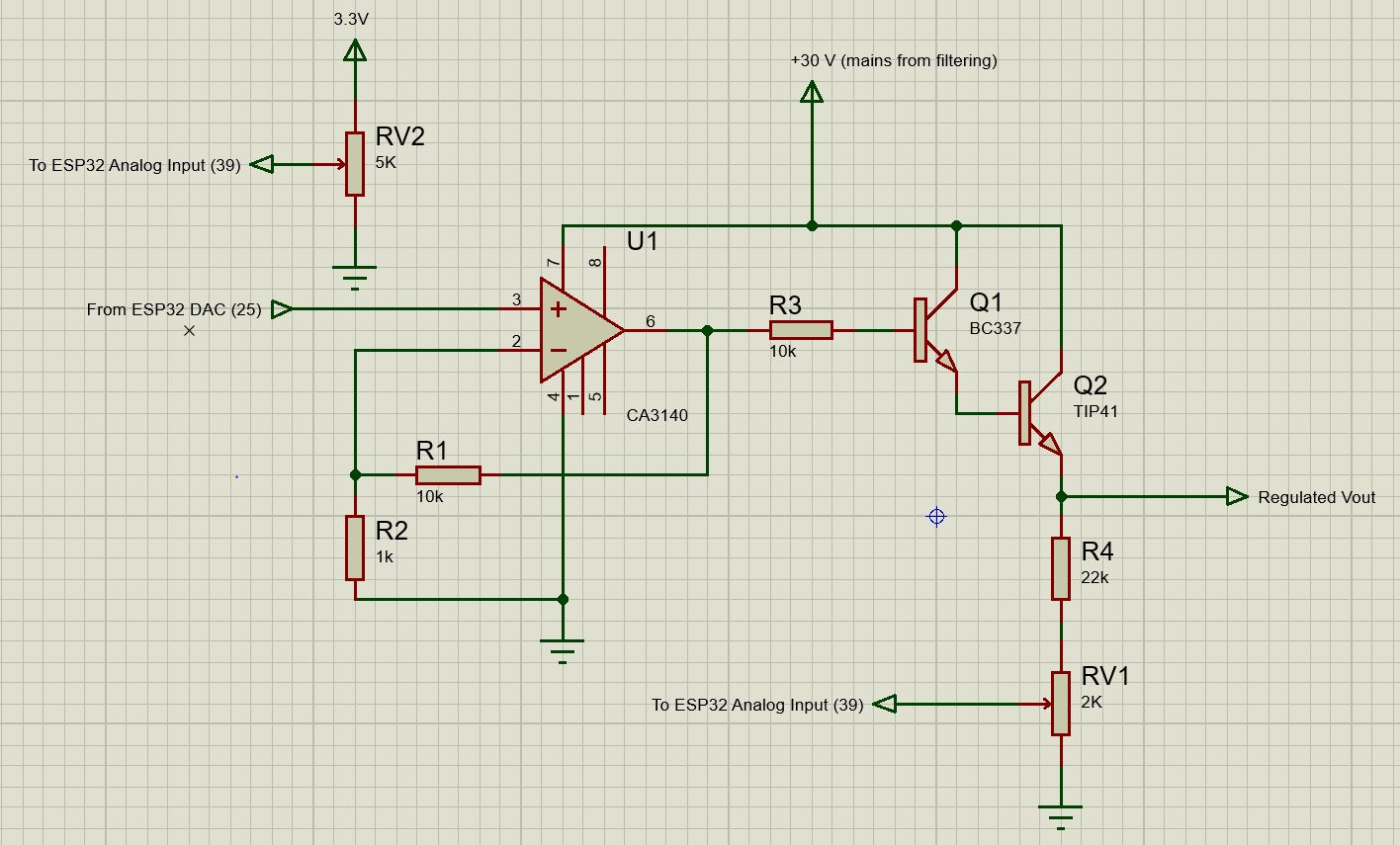
To drive the transistors on the regulator section, I'm thinking of using an opamp with the necessary dc gain to multiply my control signal (0 to 3.3 or 5V) to the full range of voltage output, which will be around 24V. The chosen one so far is CA3140, for it may be powered up to 36V.

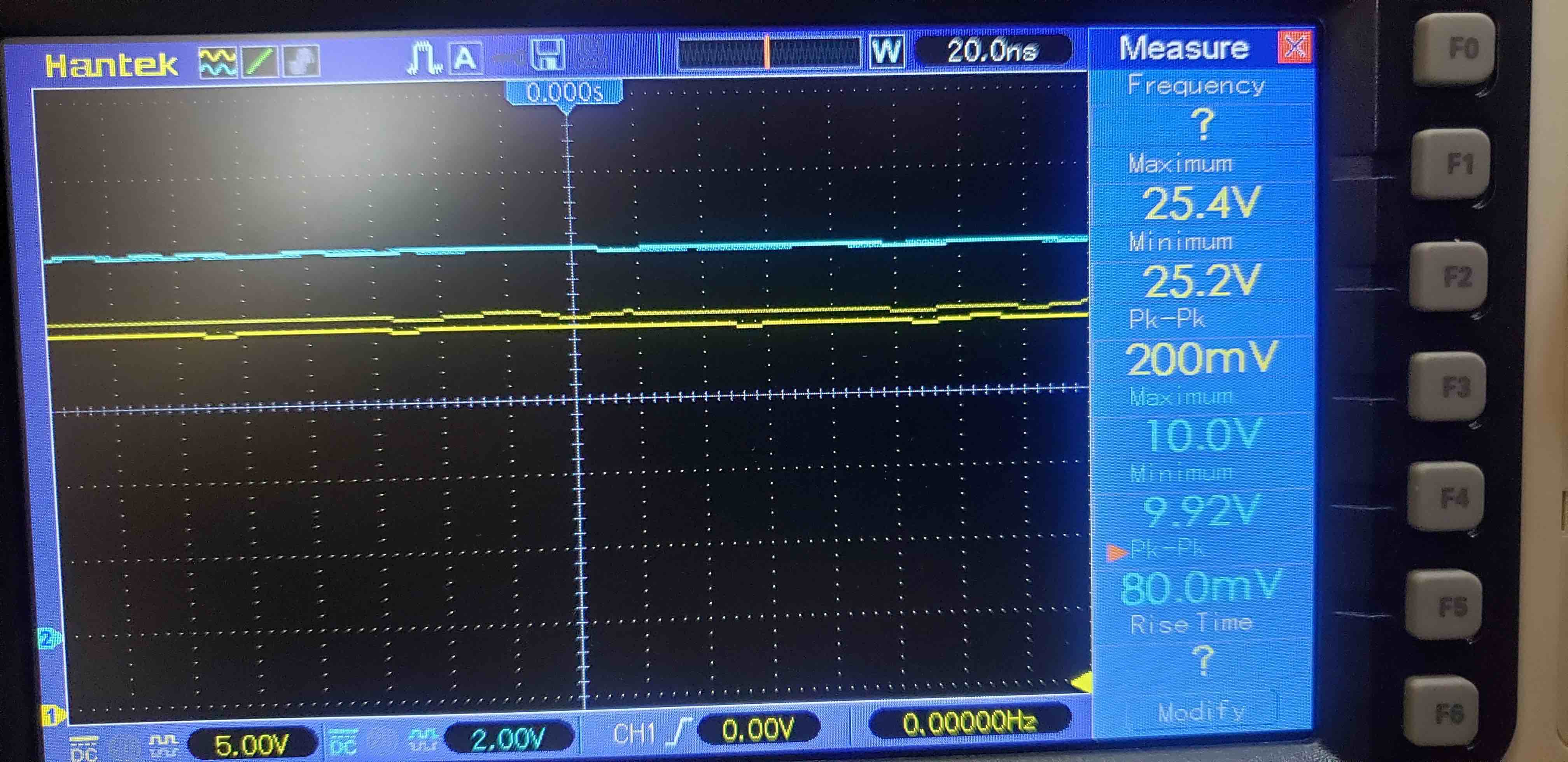
Voltage monitoring will use a simple voltage divider. I haven't made up my mind yet if I will let the adjustments to the software or simply add a trimpot to the divider. Pros and Cons?

As far as current monitoring goes, my idea is to use a hall sensor rather than a shunt. I've always used shunts, so I would like to try a different approach and save an opamp. ACS712 is an option, but I don't really know any of them. Max current should be around 3 amps.

I still don't know how I am going to set/control voltage and current .. first idea is to use potentiometers on analog inputs. But I could also go for some keyboard and/or rotary encoder.

I think of implementing most protections via software, therefore I will need very fast response mainly on current monitoring.

So the basics is that I would use a DAC for control and two ADC's for monitoring.

I happen to have some ESP32's around, they have both ADC and DAC, so it will probably be my choice.

I would like to hear your thoughts about this ideas, and see if I am missing or mistaking something.

Regards,

Paulo

Hi,
Welcome to the forum.

Please read the post at the start of any forum , entitled "How to use this Forum".
OR
http://forum.arduino.cc/index.php/topic,148850.0.html.

Thanks.. Tom.. :slight_smile:

I’m interested in the project also. It’s my understanding that analog control is much faster and so I believe the best way to achieve this is to have true analog power supply with digital controls. I’m working on an analog PID control system at the moment and analog is faster, there are many situations where this doesn’t matter, but where it’s critical it’s still analog. Perhaps there are chips that do most of the heavy lifting but we are talking about IC not necessarily digital. Thoughts?

The chosen one so far is CA3140, for it may be powered up to 36V.

No stated project design performance goals but you know you want to use a 40+ year old design first generation fet input op amp married with an ESP32 doing software based current control.

Oh, the irony. Since you’ve already made the parts selection process, what exactly do you need help with? Do you want us to just wish you good luck with the project? Yes, by all means, let’s us know how it works out.

Oh, BTW, two of those reference projects use switch mode regulators.

TomGeorge:
Please read the post at the start of any forum , entitled "How to use this Forum".

I did that .. thanks for the heads up anyway :wink:

wolframore:
I’m interested in the project also. It’s my understanding that analog control is much faster and so I believe the best way to achieve this is to have true analog power supply with digital controls.

The main reason I decided to stick to an analog design is that my other bench psu is switched. I often work with RF receivers, and I just want to make sure I won't have any switching noise.

One significant problem with a digitally controlled variable supply of any configuration is the "fail safe" provisions that prevent it supplying more than the specified voltage, particularly at switch-on. Indeed you have to figure out exactly what will happen at switch-on. :astonished:

One thing you cannot do is to include the digital system in the control feedback loop. I expect you realise this, but we have in the past had enquiries suggesting that the Arduino (or similar) might monitor the voltage and provide feedback.

WattsThat:
No stated project design performance goals but you know you want to use a 40+ year old design first generation fet input op amp married with an ESP32 doing software based current control.

Ooops ... I might be revealing my age here ...

WattsThat:
Oh, the irony. Since you’ve already made the parts selection process, what exactly do you need help with? Do you want us to just wish you good luck with the project? Yes, by all means, let’s us know how it works out.

That's not quite right, I said "so far" ... and that's exactly where I need help. Can you suggest a more suitable, modern opamp? Or a different approach using transistors, like on the reference projects? Or a different microcontroller? Or an external DAC? An R-2R ladder? Pros and Cons of each option? Those are thoughts I would like to hear.

Good luck wishes are always welcome too! :wink:

Paul__B:
One significant problem with a digitally controlled variable supply of any configuration is the "fail safe" provisions that prevent it supplying more than the specified voltage, particularly at switch-on. Indeed you have to figure out exactly what will happen at switch-on. :astonished:

I am aware of this problem and I've thought of some workarounds. One of them would be to always have the output initially blocked (by a relay, for example) and manually enable it.

Paul__B:
One thing you cannot do is to include the digital system in the control feedback loop. I expect you realise this, but we have in the past had enquiries suggesting that the Arduino (or similar) might monitor the voltage and provide feedback.

I might be on the wrong direction here ... my idea was to do exactly that: feed the output voltage to an analog port and compare it to a preset value on another analog port, and send a signal control to the regulator through a DAC, Is there a problem here that I don't see?

pfbsouza:
I might be on the wrong direction here ... my idea was to do exactly that: feed the output voltage to an analog port and compare it to a preset value on another analog port, and send a signal control to the regulator through a DAC, Is there a problem here that I don't see?

You bet! :astonished:

Such a feedback loop is far too slow to be able to control a regulated supply. It would be completely unstable. You cannot overcome this using large capacitors either.

I agree, there are things best left up to what analog does best. A digital to interface is still possible as well as other housekeeping.

Even using a fast processor, such as the ESP32 with a 240MHz clock? Wow, if that's the case my plan won't work at all :confused:

try FPGA... you might get close.

Thanks for the heads up ... I'll look into it.

1 Like

Well, let´s breadboard ...

I gave it a try, and that´s what I came up with so far:

The schematic and a picture of the mess are attached.

Here is the code (very simple):

/*
 * Digital control loop for Power Supply
 * ESP32 driving CA3140
 * Paulo Brandao
*/


#define DAC1 25 // define GPIO25 as DAC
const int potAdj = 34; // Adjust trimpot connected to GPIO34
const int voltDiv = 39; // Voltage divider connected to GPIO39
int Vadj = 0; // variable to store desired voltage
int Vctrl = 0; // variable to store actual voltage
int Dif = 0; // variable to store difference between desired and actual voltage
int ctrlDAC = 0; // variable to store DAC control

 
void setup() 
{
  Serial.begin(115200);
  delay(1000);
}
 
void loop() 
{ 
  Vadj = analogRead(potAdj); // read desired voltage
  Vctrl = analogRead(voltDiv); // read actual voltage
  Dif = Vadj - Vctrl; // compare them
  if (abs(Dif) >= 16) // 16 here because ADC is 12 bits and DAC is 8 bits
 {
 ctrlDAC = ctrlDAC + (Dif/16); // correct output if needed
 }
  dacWrite(DAC1, ctrlDAC); // send control signal to DAC
}

First impressions: Voltage range goes from 0.4 to 25V. I tested it only with very low current, 400mA max. And it worked really well! Voltage output was very stable, and even fast changes on the load didn´t cause any fluctuations on the output.

Punch list:

  • test with actual current (up to 3 amps) and another (bigger) transistor on the output
  • implement current monitoring and code for current limiting (maybe constant current as well)
  • implement display and maybe rotary encoder

ESP32 was running at 160MHz, so it can still be faster if necessary.

Regards,
Paulo

1 Like

i would like to see the output on a scope. There’s got to be some lag and switching. What’s the load and did you have capacitors on the output?

The circuit clearly shows no feedback other than digital.

Thanks for sharing, would love to see scope and further testing.

How fast is the error correction? There should be some integration in the opamp and perhaps the transistors.

Another concern is the 8 bit DAC that’s only 256 steps, that’s not giving you any quantizing or oscillation?

Hi,
OPs images.


RV2 goes to input 34, just a typo I would assume, nice clean diagram. :slight_smile: :slight_smile:
Input 34 is the OUTPUT VOLTAGE SETPOINT
Input 39 is the OUTPUT VOLTAGE FEEDBACK

int VoltSetPoint = 0; // variable to store desired setpoint voltage
int VoltFeedback = 0; // variable to store actual feedback voltage

const int voltageSetpointPin = 34; // Adjust trimpot connected to GPIO34
const int voltageFeedbackPIN = 39; // Voltage divider connected to GPIO39


Thanks.. Tom... :slight_smile:

the diagram is Proteus... I'm not convinced it works.... no scope output?

Take it easy, I have the main job to take care too ... actually this period of home office is giving me some extra time to play with projects like this.

Thanks Tom for posting the pictures this way, I haven't figured out a way of doing that yet, but I think I got it ... you will know if you see some pics along this post :wink: . And you are right there was a typo there ... actually two: RV2 goes to GPIO34 and R3 is 1k instead of 10k.

Wolframore, I did some more testing today, and even got you some scope images. I'll post pictures of the screen here, since I don't know a way of saving a bitmap or something like that. Suggestions are welcome!

There's no noticeable lag, response is really fast. Of course, as more features are implemented, more cpu cycles will be necessary and response will slow down, let's see if it will be an issue.

There's no noticeable quantization either, and I think that is kind of expected, since the control signal and output are supposed to be constant over time.

What's new:

I added a third transistor on a heatsink, a 2SD1047, to handle higher current. Obviously also moved one end of the voltage divider to the emitter of this new transistor.

Here is the scope picture of the system with no load:


Input voltage is 32.4V and output set to ~10V (9.8V)

Here the picture with a 1 amp load


Input voltage dropped a lot, down to 25.4V; output voltage raised a little, to 10.0V

Here the picture with a 2 amp load


Input voltage dropped severely, this is the limit of my transformer. Output raised a little more, to 10.3V, this is weird ...

In both 1 and 2 amp loads input ripple was between 200 and 400 mV, there was only a 2200uF filter. Although, ripple on the output was steady at 80mV

Esp32 was being powered by computer USB port, and grounds were connected.

About the voltage raise: I could notice that there was a little raise on the voltage set trimpot, which means that the 3.3 line has raised a little bit with higher currents. I still have to figure this out, but it doesn't seem too complicated to solve. Any ideas?

That's today sprint.

Regards,
Paulo

thanks that's pretty cool... could you zoom in to the output... I like to see it working... any way of putting active load on it?