Yet another UPDI programmer . . . but possibly the ultimate?
This simple to make UPDI programmer is a further development in a long quest (started here: ATtiny1614 / USBTTL adapter for UPDI programming and serial console access ) to have a programmer which, with one single USB adapter, could seamlessly, in a smooth workflow, handle both the UPDI programming and the serial communication with the target new series AVR devices together with the megaTiny core.
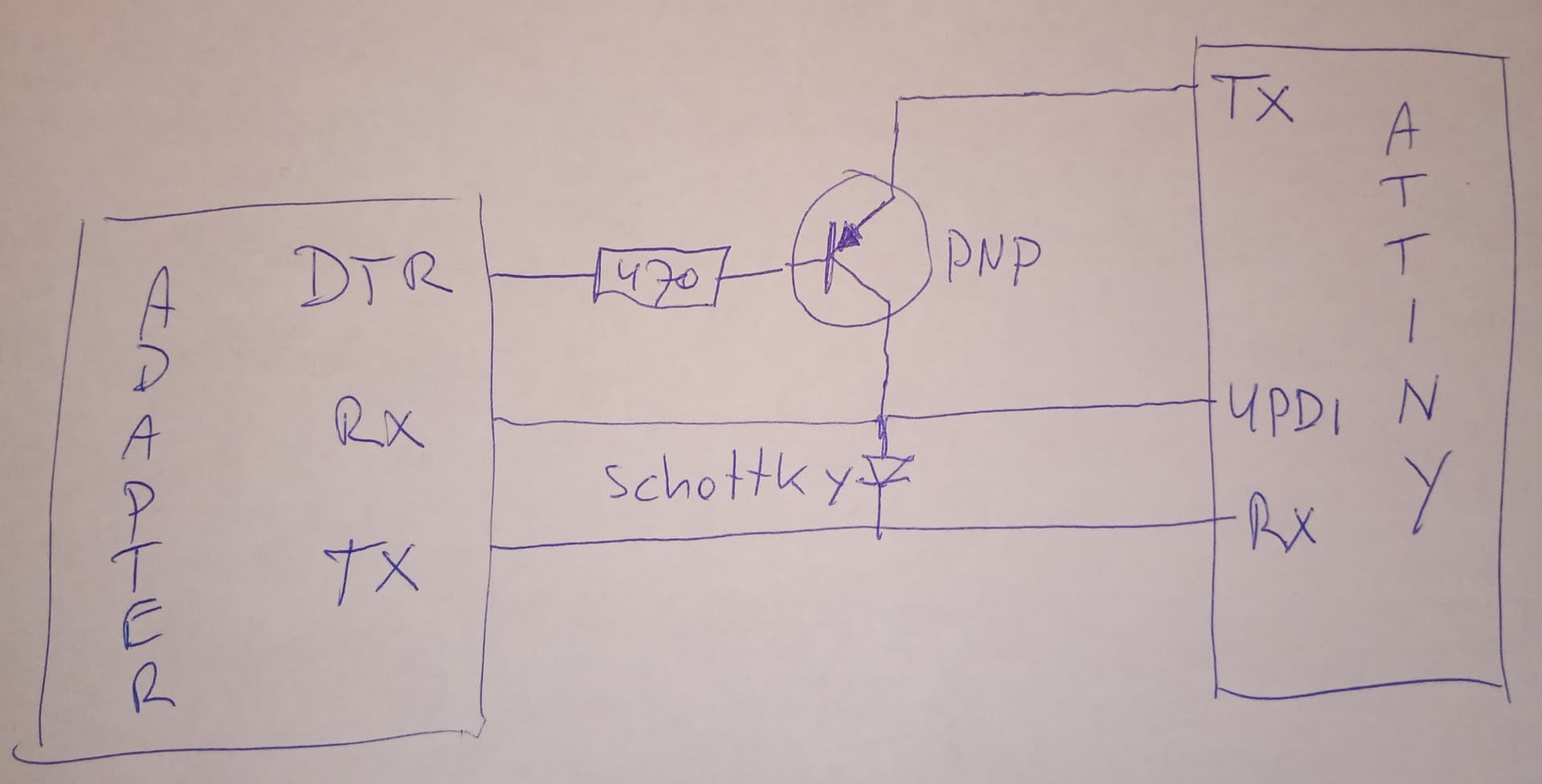
Yes, you always had the option of using a bootloader, but this is a miserable experience especially on the low pin count devices and, of course, you always do something similar with two USB/TTL adapters, one of which would be configured for UPDI, and two USB cables to achieve the same results. Then came solutions which used analog switch ICs to, with varying degrees of success, dynamically repurpose a single USB/TTL adaptor for the dual functions of programming the device via UPDI then swapping the role to that of a simple USB/TTL adaptor to handle the serial comms. Now finally the development described here, as the ultimate in both ease of use and ease of construction, using the now available CH342 module which presents itself to the PC host as USB-2 hub and additionally provides two USB/UART interfaces. All this, incidentally, without the need for any special drivers (at least not for Windows) other than those required for the ubiquitous CH340 devices found on many Arduino clones.
Some time ago, @DrAzzy, who refined serial UPDI to make it usable with AVR, wrote a prophetic piece on the direction of future developments in this area which, in retrospect, appears quite visionary from the perspective of the current state of the art, accurately predicting the emergence of devices such as the one described here. It can be read here (Ref 2 below).
Anyway, to visualise what it can do, see this simple screen shot showing two active comms channels, one for the UPDI interface and one for the USB/UART interface. IDE 1.x is used here for simpler simultaneous handling of 2 instance of the serial monitor. The target device is, incidentally, an ATtiny 1614:

This is how it appears in the Windows device manager:

Hardware build and schematic
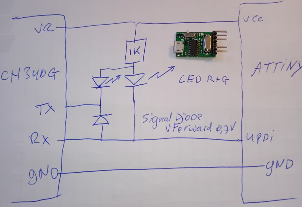
Here is some of the detail about the device and what it looks like. It consists of a module CH342 USB-2TTL, stocked by a number of AliExpress retailers (I got mine from YourCee https://www.aliexpress.com/item/1005008001334082.html) and a small addon circuit consisting of two resistors and a diode together with a number of mainly optional connectors. Serial channel 0 (TX0/RX0) is dedicated to normal serial activities. Serial channel 1 (TX1/RX1) is dedicated to the role of UPDI programmer. Note, however, that a hardware modification, described later, has to be applied to the CH342 module to make it function as a UPDI interface. That is, the channel 1 leds have to be disabled and without this it simply will not work.
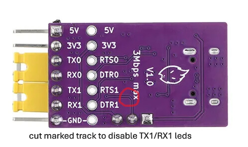
The complete schematic of the CH342 USB-2TTL module is included for reference together with that of the add-on circuit. Since I don't have a method of measuring the value of capacitors in circuit, I've left the values blank. The module design uses a common but crude method of handling the leds to signal serial activity on the RX and TX pins which affects the signal presented to the target UPDI port. In practical terms the solution is to disable the leds. The recommended way is to cut the PCB track identified in the picture. Other methods are removing the leds (or their series resistors). Any complete board (re-) design could use a transistor or similar component
to less invasively control the leds and without damaging the signal, the state of which, the leds are supposed to indicate. Note. Before you even start, verify the existing functionality of the CH342 USB-2TTL module so see the troubleshooting guide below for ideas on how to test it.
Schematic for both the CH342 USB-TTL module and the prototype board:
CH342F_V0_01.pdf (170.0 KB)
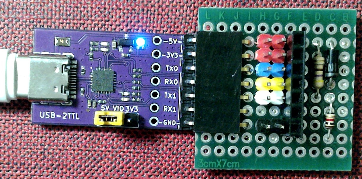
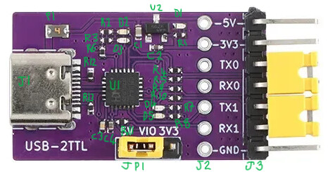
CH342 USB-2TTL module front with components labelled to match the schematic:
CH342 USB-2TTL module rear showing track to cut (red circle)
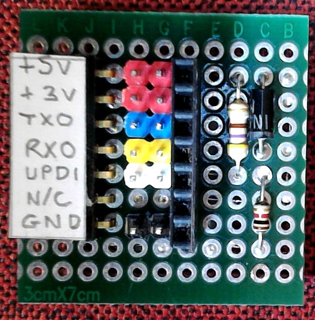
Prototype board front:
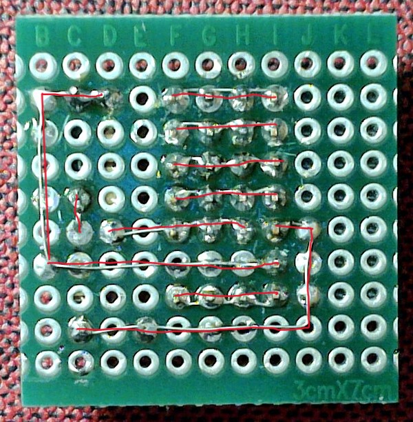
Prototype board rear (bus wires highlighted)
Performance tests
-
only tested with the MegaTinyCore [ref 2 below] and Arduino IDE 1.8.19 / Windows 10
-
The device appears to retain the same allocated com ports across sessions. I tried alternatively with the two devices I purchased and this behaviour was consistent.
-
Seems to work at 230400 baud (and of course 57600 baud) for UPDI at 5v.
-
460800 baud worked with the "delay" option and failed, producing a screen load of error messages, without the delay. Again at 5v.
-
Attempts to use 921600 baud rates showed these were not actually attainable and the operation quietly fell back to 115200 baud proceeding to a successful result, albeit at a lower speed.
Troubleshooting
There is really not so much to go wrong assuming the basic testing shows the CH342 USM-2TTL is OK. However, if Window (or your OS) does not even recognise the device then look here first:
-
Ensure that you are using a USB "data" cable and not a simple "charging" cable.
-
If you are using Windows and have never previously used a device with a CH340 USB chip then, in this unlikely case, you have to find instructions to load the necessary drivers. See Ref 4 below.
If you get that far and still have problems:
-
You should previously have tested that the CH342 USB-2TTL device is capable of performing as a normal USB/UART device on both channels. This can be achieved by doing a loop back test using the 2 supplied jumpers and checking that what is typed in the serial monitor is echoed back. Do this for both COM ports.
-
You must also have successfully disabled the TX1/RX1 leds using either the suggested track cut or some other method. Don't even dream of getting it to work properly without this necessary step.
-
You have correctly assigned the two COM ports, that the device presents, to the respective functions UPDI and standard serial. Look in the device manager under Ports. The COM port for UPDI (TX1/RX1) will be labelled something like USB-Enhanced-SERIAL-B CH342. The "A" side is used for the normal serial function (TX0/RX0) [at least that is what my limited testing here has shown but I suppose the enumeration could be inverted]
-
Check that the jumper selectable voltage matches the selected voltage delivered to the target device. If the target device is also powered separately, disconnect the power output from the programmer.
-
If you are still having trouble, and have not already done so as a pre-build activity, then do a breadboard build of the 3 resistor / 1 diode circuit and check that out.
Alternatives and further improvements.
There is a similar chip to the CH340F as used in the USB-2TTL module, that is the CH340K. It has less pins broken out but would also function in this role and may be easier to hand solder. However, since it does not break out the RTS pin it cannot easily be used in addition as an FTDI type adaptor for programming the original series AVR or similar chips.
The addition of a 12v circuit could also be desirable to handle cases where the target's UPDI pin has been reassigned to another purpose and a high voltage programmer function is required to restore the device to its factory condition.
References:
- Spence Kondo megatiny core (UPDI stuff) AVR-Guidance/UPDI/jtag2updi.md at master · SpenceKonde/AVR-Guidance · GitHub
- Spence Kondo (general stuff including some visions of superior serial adapters) GitHub - SpenceKonde/megaTinyCore: Arduino core for the tinyAVR 0/1/2-series - Ones's digit 2,4,5,7 (pincount, 8,14,20,24), tens digit 0, 1, or 2 (featureset), preceded by flash in kb. Library maintainers: porting help available!
- CH342 datasheet (english) https://cdn.sparkfun.com/assets/8/e/f/5/1/CH342_Datasheet.pdf
- CH340 driver installation How to Install CH340 Drivers - SparkFun Learn