Project: Arduino control (digital and/or PWM) of high current automotive elements; stage 02
Introduction
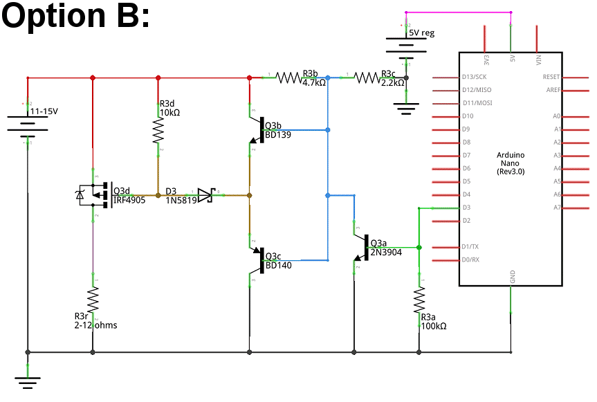
For this stage, the goal is PWM control of fairly significant current loads. This project will be managing two elements, at 2-7 amps per element (200 watts total).
Note: I explored some of this project in these forums about a year ago. Various circumstances didn't allow me to pursue this fully at the time; I'm now taking another run at it. I must say that the support and contributions from various members here has been amazing. For everything in the past, and everything in the future, thank you one and all.
A bit about me: I'm fairly new to Arduinos and electronics; I'm learning fast, and having a blast. ![]() I have plenty of experience with linear programming (20+ years), and next to zero experience with object oriented and event-driven programming.
I have plenty of experience with linear programming (20+ years), and next to zero experience with object oriented and event-driven programming.
I've divided this project into manageable (at least for me) chunks. This breakdown may be changed on the fly and/or after the fact before the completed project is published.
01 [DONE] Detect switch to ground (I know; not very appropriate considering where this topic went).
This stage deals with dual-switched (+V and ground) control of power provisioning to the Arduino and main loads. It also deals with switch state info to the Arduino.
02 [CURRENT] Automotive: High(er) current control and management
This stage deals with using the Arduino to provide digital and/or PWM management of fairly high current loads (up to 7 amps per element).
03 [UPCOMING] This stage will add some minor elements and is not likely to have any significant impact.
04 [UPCOMING] In the last stage, programming will be explored. (This stage may be broken into smaller chunks.)
05 [UPCOMING] Review and documentation
06 [UPCOMING] Publication of completed project
Anywhere along the way, I would be happy to explore alternate uses of various elements, potentially useful additional elements, etc.
02 Automotive: High(er) current control and management
For this topic, all schematics have power provisioning, control, switch state info, etc. abstracted. I show two power sources: 11-15V (from existing automotive services) and 5V reg (from a Pololu 24VxxF5). All switching, etc. is left out as it's not important or connected to anything in this stage.
Onwards...