I am putting together a circuit to trigger one of our lasers.
The triggering requirement are
pulse voltage between 4.5 and 5V
duration: at least 10 µs
Rise time: ideally <300 nS
connection to the instrument trigger port: coaxial BNC
I was trying to use component I already have:
Arduino (Mega or Uno R3)
NE555P (Timer Transistor)
TIP121 (NPN transistor)
I put together a circuit following the "step4" of this guide
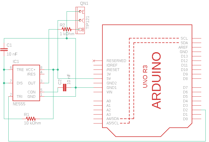
You can check the attached scheme Arduino_NE555.png. In this case, the TIP121 was not included in the circuit.
Briefly: I used the 5V out of the arduino, a 10nF capacitor and a 10 kOhm resistor
With the RC value I used, the theoretical pulse width should be ~110 µs.
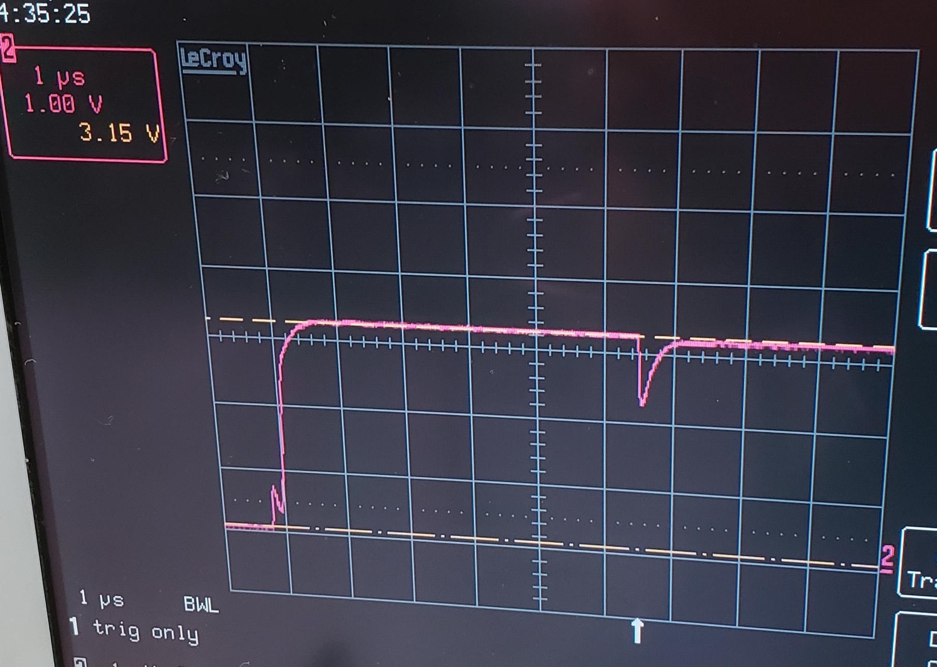
Checking with an oscilloscope, I measure ~130 µs. The problem is, the voltage is not enough. I get about 3.15V (555_Only_1.jpg).
In addition, I see a bump when the signal is rising and a small drop (~ 1V) after ~ 6 µs, which quickly goes back to 3.15, somewhat similar to a capacitor behaviour (555_Only_2.jpg).
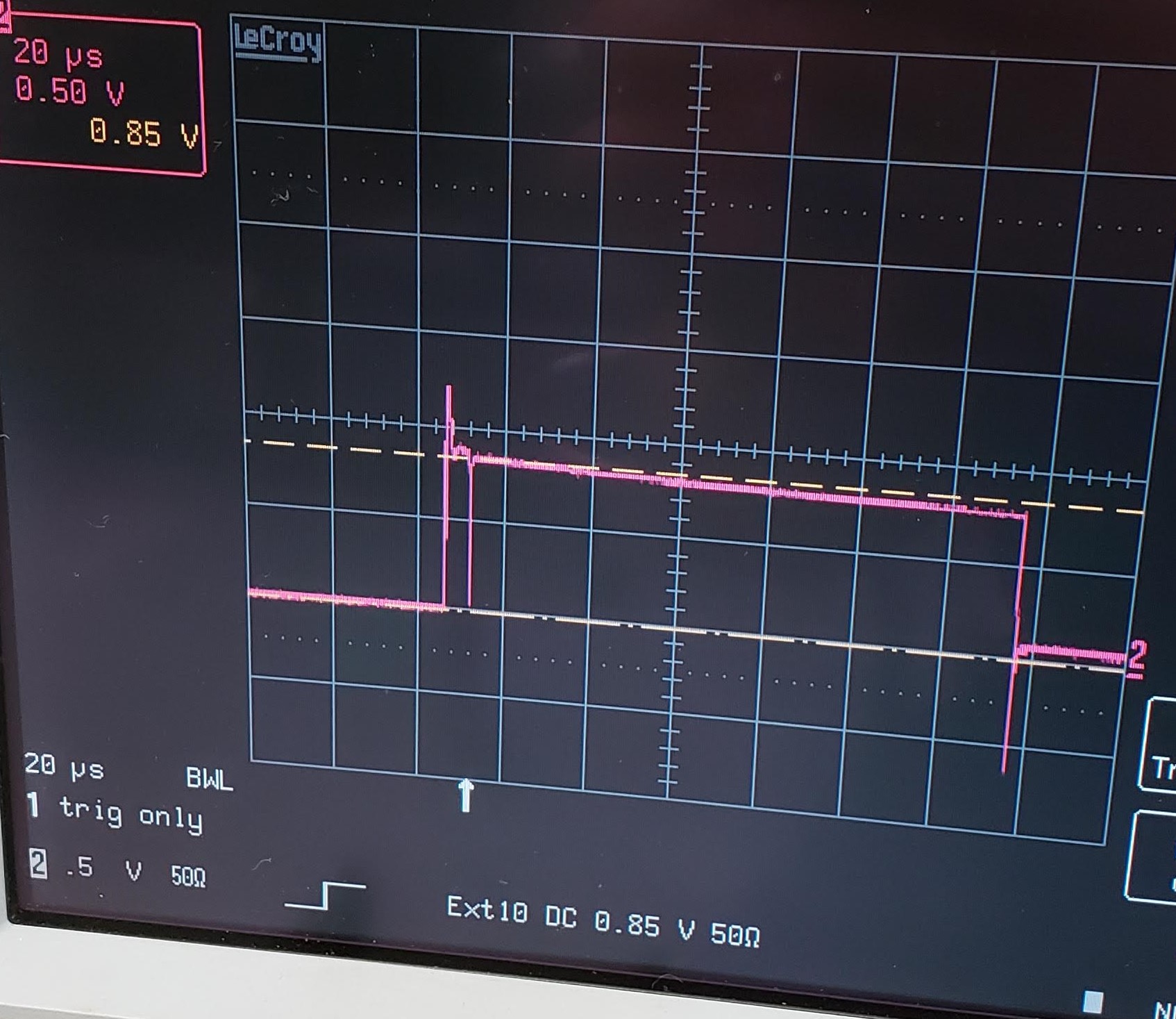
I thought about using the timer together with a TIP121 transistor (see scheme Arduino_NE555_TIP121.png). In this case, the voltage at the emitter is ~0.85V (555_TIP121_Em.jpg) and at the collector I measure a loss of ~1.15V (555_TIP121_Col.jpg).
In both cases, I was pulsing the signal with the arduino setting the digital pin 2 LOW, then bach HIGH again and delaying the loop for 10 ms.
I understand that using the 555 alone will not accomplish the goal because of the voltage drop associated with the IC. At the same time, I was wondering about the trends shows in the zoomed in image: is there something wrong in the schematic itself? Do I need to rely on a different voltage supply?
I am not sure what I got wrong in the scheme with the transistor.
[u]Here[/u] is a transistor driver with the required pull-up resistor. (You also need to leave-in the base resistor.) A single transistor is normally an inverter, and I don't remember if you can get a negative timed-pulse out of a 555 or if you'll need to add another inverter stage...
...It's been awhile since I used a 555 and I'm surprised to learn that it doesn't go closer to Vcc, but the datasheet confirms what you're seeing.
My guess is that he biggest thing was that you didn't post one.
Actually he did, but he didn't use the "normal" schematic symbol and he didn't show any connection to the emitter...
But if it was connected to a resistor between base and ground you would have an emitter follower and as the TIP121 is a darling pair and not a transistor you will only get 1.4 V less out than you put in at the base.
Grumpy_Mike:
My guess is that he biggest thing was that you didn’t post one.
Several photos of a scope mean very little without knowing where on a circuit you are taking the readings from.
The picture have titles.
"Arduino_NE555_TIP121.png" is the overall schematic. I actually tried two configurations, 1 without the transistor and one with the transistor. I noticed that the scheme does not show the emitter connected to the ground. The attached does.
"555_only_1.jpg" means that there was no transistor in the circuit. I read the output of the 555 (pin 3)
"555_TIP121_Em.jpg" means that I was reading the emitter of the transistor
"555_TIP121_Col.jpg" means that I was reading the collector of the transistor
Grumpy_Mike:
Sorry I missed that.Good job because it would short out the supply.
But if it was connected to a resistor between base and ground you would have an emitter follower and as the TIP121 is a darling pair and not a transistor you will only get 1.4 V less out than you put in at the base.
That explains the voltage issue, thanks.
Need a line drive then? or perhaps I should go with a different approach to create the square wave? Perhaps a 74LS121 ?
Not sure why you're fiddling with an ancient NE555.
Those chips need a 15volt supply to reach proper specs.
At 5volt VCC they can only sink (LOW) ~5mA and sourcing (HIGH) drops to <2volt with some current.
What is the input impedance of this "laser". BNC indicates a possible 50 ohm termination resistor.
An Arduino can generate those pulses cleanly, but you might have to look at a mosfet driver chip to boost the Arduino signal to the voltage/current/impedance you need.
How long is that 'transmission line' (coax cable) to the laser.
The wrong cable and termination will kill your rise/fall times.
Leo..
One of the projects I was involved in, prior to my retirement, required an accurate repeatable pulse that was not practical to use a 555.
I found the idea device. The whole family require only 3 resistors to set them up. There is even an app to take the agro out of calculating the resistor values.
Check them out.
FabrizioDonnarumma:
I was trying to use component I already have:
Arduino (Mega or Uno R3)
This one should be dead easy - assuming your coax cable is not very long (too high stray capacitance giving too long rise time). I'm assuming the input your signal is connected to is high impedance.
NE555P (Timer Transistor)
Now if you take an more modern 555, anything based on CMOS instead of outdated BJT technology, this should also work just fine.
An NE555 won't do because indeed the output voltage is about 3.4V when Vcc = 5V, and your 100 µs pulse is pretty short for a device that's rated to do up to 100 kHz, giving a theoretical minimum 10 ୖµs pulse. Also it's output rise time can be as much as 300 ns (15 pF load).
On the other hand a TS555 has an output of guaranteed minimum 4.4V at Vcc = 5V, and an output rise time of 25 ns (for load capacitance 10 pF).
These numbers are from the NE555P and TS555 datasheets.
Wawa:
Not sure why you're fiddling with an ancient NE555.
Had them in the lab and it seems they might work.
Those chips need a 15volt supply to reach proper specs.
At 5volt VCC they can only sink (LOW) ~5mA and sourcing (HIGH) drops to <2volt with some current.
... and now I know they won't work.
What is the input impedance of this "laser". BNC indicates a possible 50 ohm termination resistor.
Yes, 50 ohm
An Arduino can generate those pulses cleanly, but you might have to look at a mosfet driver chip to boost the Arduino signal to the voltage/current/impedance you need.
How long is that 'transmission line' (coax cable) to the laser.
The wrong cable and termination will kill your rise/fall times.
Leo..
I can place the circuit close to the BNC trigger input of the instrument and reduce the length of the cable to 10 " or less.
IamFof:
One of the projects I was involved in, prior to my retirement, required an accurate repeatable pulse that was not practical to use a 555.
I found the idea device. The whole family require only 3 resistors to set them up. There is even an app to take the agro out of calculating the resistor values.
Check them out.
FabrizioDonnarumma:
I can place the circuit close to the BNC trigger input of the instrument and reduce the length of the cable to 10 " or less.
50ohm termination (100mA@5volt) can't be safely driven by an Arduino pin, so you must use a buffer anyway.
Don't restrict yourself. Tell us what you really want, and we will try to find the parts needed for that.
There is no practical wire length restriction if you use the right cable and drive and termination impedance.
Google "transmission line termination".
The correct way for a clean 5volt pulse at the destination is to use a 10volt pulse with 50ohm resistor in series at the drive end, and a 50ohm termination resistor to ground at the destination. This 1:1 voltage divider will drop this to 5volt at the destination, and there is no frequency distortion assuming you use 50ohm coax. As said, look at mosfet drivers (powered with 10volt).
A NE555 powered with ~12volt might be ok for experimenting, but don't forget the two 50ohm resistors.
Leo..
No the circuit in reply #4 is still wrong. It will short off the supply. You need the resistor in the emitter, collector to, 5V and no base resistor for an emitter follower.
Wawa:
50ohm termination (100mA@5volt) can't be safely driven by an Arduino pin, so you must use a buffer anyway.
Don't restrict yourself. Tell us what you really want, and we will try to find the parts needed for that.
There is no practical wire length restriction if you use the right cable and drive and termination impedance.
Google "transmission line termination".
The correct way for a clean 5volt pulse at the destination is to use a 10volt pulse with 50ohm resistor in series at the drive end, and a 50ohm termination resistor to ground at the destination. This 1:1 voltage divider will drop this to 5volt at the destination, and there is no frequency distortion assuming you use 50ohm coax. As said, look at mosfet drivers (powered with 10volt).
A NE555 powered with ~12volt might be ok for experimenting, but don't forget the two 50ohm resistors.
Leo..
The requirements are as follow
output pulse voltage between 4.5 and 5V
duration: at least 10 µs
Rise time: ideally <300 nS
instrument trigger port: coaxial BNC, with a 50 ohm tee terminator
I would like to use an arduino to generate the desired frequency (Which is a number between 1 and 200 Hz). The reason being that I can easily control the arduino within other environment (e.g. LabVIEW). I already know how to program the arduino to accept commands that would set the desired frequency and start/stop the trigger.
What I miss is a triggering circuit that generates the square wave described above.
Wawa:
So not a constant stream of needle pulses, but some extern trigger
Correct. To be clear, what I want to achieve is the ability to externally trigger this laser at a variable, operator defined, frequency. A trigger pulse has the characteristics I described.
I plan to program the arduino to accept 3 commands: a frequency setting command, a start command and a stop command.
Once the user send the start command, the arduino will produce a pulse at the frequency specified by the user and the triggering circuit will produce the correct square pulse.
Please note that the pulse duration can be fixed (I am testing what would be a reasonable pulse duration using a DG535 pulse generator).
Wawa:
A common Arduino Uno has AFAIK a 4µs resolution (steps), so 8µs or 12µs won't be a problem.
That is for the micros() function. The delayMicroseconds() doesn't have this limitation.
For a clean, reliably timed pulse of that duration I'd look into timer interrupts, but not sure if OP needs it that precise as they say "at least 10 us" which implies some leeway there.
For exact timing of pulses use a timer and its Output Compare unit (similar to generating PWM). Interrupt way is somewhat easier but may introduce some jitter (mostly depending on other enabled interrupts).
wvmarle:
That is for the micros() function. The delayMicroseconds() doesn't have this limitation.
For a clean, reliably timed pulse of that duration I'd look into timer interrupts, but not sure if OP needs it that precise as they say "at least 10 us" which implies some leeway there.
Based on this reply, I run a quick test. I was curious to see how a pulse generated through the arduino would look like
I was wondering what the nature of the fluctuations was. I used two 1-foot long coax cable with a 50 ohm terminator and two probe clip wires (about 10 inches long) to connect them to 10-inches long jump cables that were plugged on port 2 and 3 of the arduino. I run it just for 10 sec to get the video.
If I use a TC4420 as Leo suggested, I should be able to drive the voltage I want with this square pulse, am I correct?
Smajdalf:
For exact timing of pulses use a timer and its Output Compare unit (similar to generating PWM). Interrupt way is somewhat easier but may introduce some jitter (mostly depending on other enabled interrupts).
Exact timing is not required.
The pulse must be > 10 µs, but it could be 20, 50, 100 µs. The max rep rate is 200 Hz anyway.
About jitter: the manufacturer recommended a rise time of < 300 ns. The square pulse I recorded using the arduino with the code in my previous reply has ~ 100 ns rise.