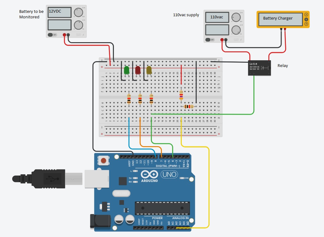
I am using a voltage divider to monitor a 12 volt battery charge state. The battery is part of a solar panel system for my home. I want to turn on a 110vac battery charger when the battery voltage falls to 11.0 volts. The r1 value is 3.26K and r2 is 1K. The values I get on the analogRead is ~570 when voltage at divider is 11.77v I do not understand the math to convert the analogRead value into a voltage that is correct when the input voltage to divider ranges from 10.0v to 15.0v Another problem is when the voltage goes above about 13.7 v the analogRead value seams to get very small. I am lost.
Thanks jremington for you reply. I have read until I am blue in the face. I know about voltage dividers and how they work. The problem occurs with the analogRead giving a integer not a voltage. So in the code you have to handle things like resistor values, tolerances, and conversion to a float voltage value to test against. My divider gives me a 2.38v to 3.78v input to the (a2) pin. The battery voltage at the divider is 11.56v to 13.7v. my code
Instead of integers, use floating point numbers and the problem goes away.
Rather than something this:
voltage = ((sensorValue1 * xxxxx)/1023);
Use this (1023 is not the correct divisor):
sensorValue1 = sensorValue1/5.0; //take average of 5 measurements
voltage = (sensorValue1 * 5.0 * 4.26/1024.);
For best accuracy you need to measure the Arduino Vcc with a multimeter and substitute that value for 5.0. For example, when powered by USB, Vcc may be around 4.5 V.
You may also need to measure the resistance values to take into account their inaccuracy. The ratio to use is (R2+R1)/R1 instead of 4.26.
Or, proceed the way you have and calculate a "correction factor" from the measured voltage. If I understand this correctly:
The values I get on the analogRead is ~570 when voltage at divider is 11.77v
Then the voltage calculation is
sensorValue1 = sensorValue1/5.0; //take average of 5 measurements
voltage = (sensorValue1 * 11.77/570.);
Finally, fix a serious error in your code (you were initializing the wrong variable):
jremington:
For best accuracy you need to measure the Arduino Vcc with a multimeter and substitute that value for 5.0. For example, when powered by USB, Vcc may be around 4.5 V.
For that reason (instability) it might be better to drop battery voltage with the divider to 1volt,
and measure that with the internal 1.1volt Aref enabled in setup().
A resistor ratio of 1:15, e.g. 2k2 and 33k, is good for ~16.5volt max.
Leo..
Wawa:
For that reason (instability) it might be better to drop battery voltage with the divider to 1volt,
and measure that with the internal 1.1volt Aref enabled in setup().
A resistor ratio of 1:15, e.g. 2k2 and 33k, is good for ~16.5volt max.
Leo..
Note that the internal reference needs calibrating for each chip, the datasheet says it can be anywhere
from 1.0 to 1.2V. Careful with the ground wiring with such low voltages, do not share the voltage sense ground
wire with anything carrying current or you risk injecting noticable error voltages into the measurement.