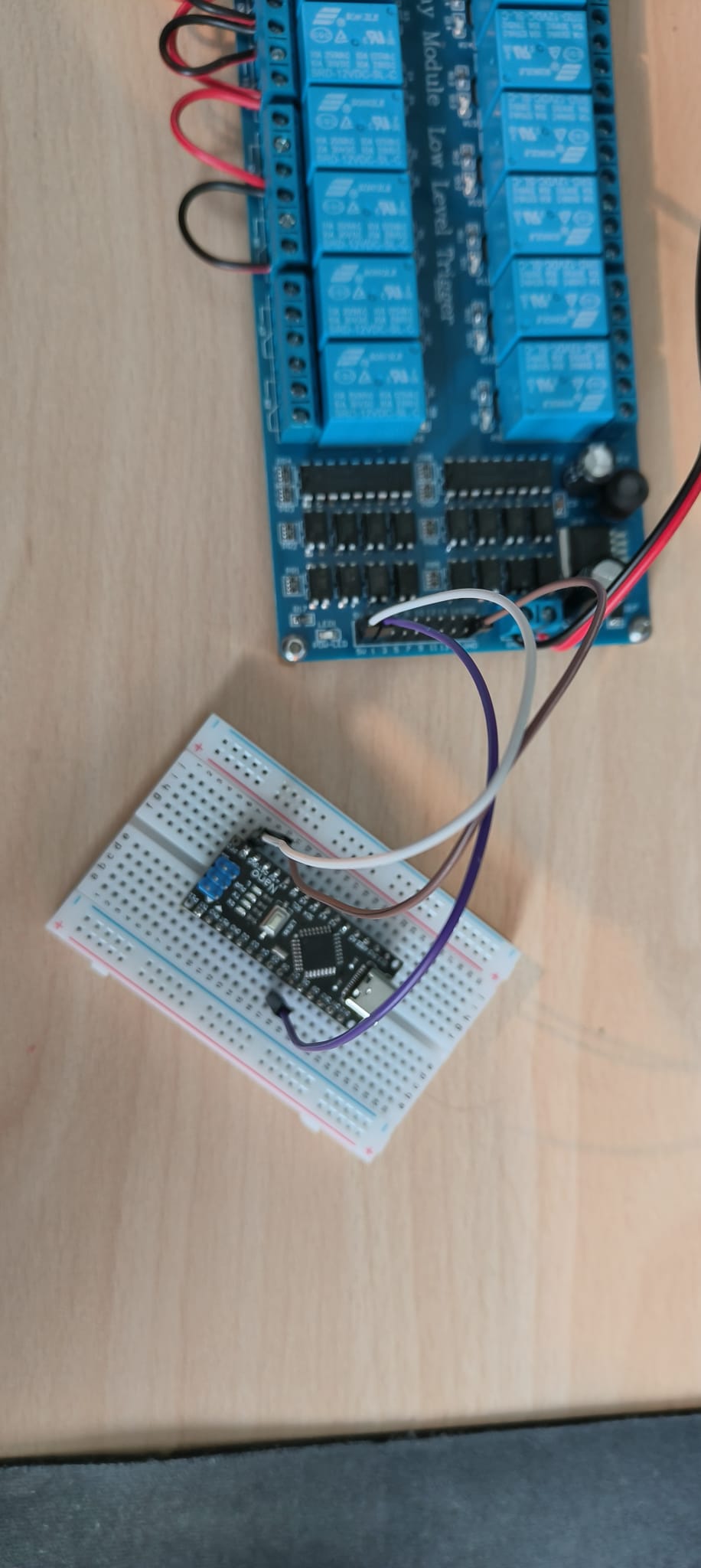
The 5V pin seems to be a output pin as I have measered it and when i connect it to the 5V of a arduino it burns out. I should be able to power the arduino with the 5V and the GND from the relay board. When I connect 5V to VIN and GND to GND the arduino is powered, but the relay just stays triggered. I figuered out that with the 5V to the VIN and de arduino powered with something else (my pc through USB in this case) and the GND form the relay board disconnected from the arduino it works as intended. I would like to just power the arduino with the board but I am not sure if that is even possible at this point.
I have found some conflicting info on here but no solutions to the same problem I am having.
Is there anyone who has had a similar issue with a board like this? Or anyone who could just help figure this one out? Thanks in advance.
The code I use to switch the relay (just a single to test it):
int8_t relayControl = 7;

// the setup function runs once when you

//press reset or power the board

void setup() {

// initialize relayControl pin as an output.

pinMode(relayControl, OUTPUT);

Serial.begin(9600);

}

void loop() {

digitalWrite(relayControl, HIGH); // Turn off

Serial.write("HIGH");

delay(5000); // wait for 5 second

digitalWrite(relayControl, LOW); // Turn on

Serial.write("LOW");

delay(5000); // wait for 5 second

}
In that case you should either decide to power the Arduino with it, or leave it unconnected.
Usually only common GND is required.
Where did you get the board ? (link please)
again it should be possible if it is an actual 5v output, but this does depend a bit on what kind of regulator is used on the board (and for what) You could of course just power Arduino from 12v through Vin
When I connect the arduino to an external power source and connect the GND it always stays triggered. If I disconnect the GND and connect the 5V to the VIN it works as intended. connecting neither GND or 5V gives no result at all.
It deffinatly is an output but i somehow measure 12V instead of 5V
EDIT: Connected to a pc with usb and 5V to VIN it works as intended. Connected to a completly seperate powersupply and 5V to VIN it also works as intended. So I think that creating any comon ground between the arduino and the relay board causes the relay to stay triggered
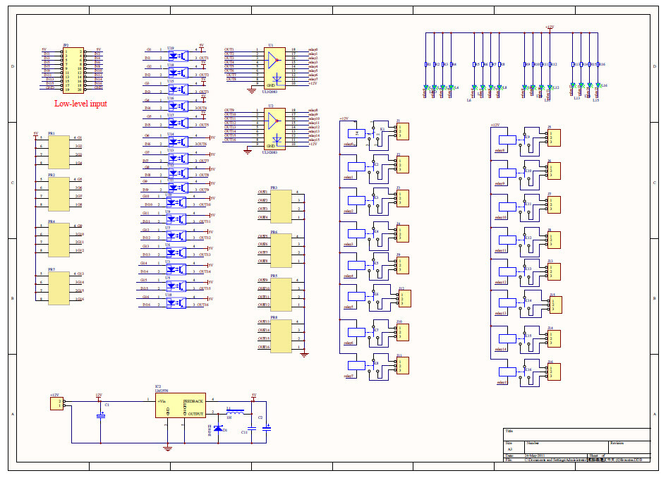
I don't completely understand the schematic as I am a noob when it comes to this.
The explanation with the link makes it better, but this doesn't really explane the problem I am having with the GND being connected to arduino making the relay stay triggered. Or am I inturpriting something wrong?
I'd wager that if all the Arduinos destroyed by beginners with these idiot relay boards were thrown into a pile, they would make a cone to rival Mt. Fuji.
This particular relay board is even worse than the commonly used one you are thinking of.
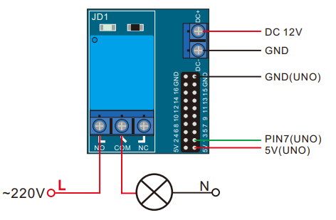
This board does not have the JD-Vcc / Vcc jumper, it has an on-board regulator that supplies 5V to the Vcc pin, so that the control board (the arduino) can be powered from the relay board power supply. This makes the opto-coupler useless for electrical isolation.
When powering the Arduino from this relay board, the Vcc of the relay board would be connected to +5v pin of the Arduino, and the Gnd pins of the relay board and Arduino are connected together. No connection to the Vin of the Arduino and no USB cable connected.
There should be 5 volts between the Vcc pin and the Gnd pin of the relay board, with no connections made to the Arduino. If this measures anything other than 5V, then something is wrong on the relay board, or possibly you have a 12V version of the relay board.
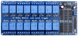
This seems to be the infamous 16-channel board from Sainsmart, with a design fault.
Opto couplers, but no user selectable opto isolation. Opto isolation is a plain lie on their website. Only 2/4/8 channel boards with a JD-VCC jumper have opto isolation.
Ground and 5volt of this board should be connected to ground and 5volt of the Nano. If something burned out, than I guess you did something wrong, or you have a faulty relay board.
Note that the inputs are active LOW.
You should use these lines in setup().
pinMode(relayPin1, INPUT_PULLUP); // first enable internal pull up
pinMode(relayPin1, OUTPUT); // then set the pin to output
A LOW will turn the relay ON, a HIGH will turn it off.
Leo..
True, not needed to control the relays, but it is needed if you also want to power the Nano from that relay board. That board has a 12volt to 5volt buck converter to be able to do so.
Powering the 5volt pin of the Nano from the 5volt pin of that board should be fine.
Leo..
Edit: Powering the Nano from USB and not powering the relay board at the same time could burn out the backflow protection diode of the Nano and/or the voltage regulator of the Nano. Maybe that's what went wrong.