Can't turn on 12v relay with output pins

I am having issues turning on any of the relays on my 8 channel 12V relay board.

Relay Board: Amazon.com

I have the board connected to a 12v power supply with a common ground between the board and the arduino. The arduino is plugged into a laptop.

The issue is that the output pins, in this case pin 12, can't turn on the relays even though I am measuring 5v from the pin. However, If I use the 5v or 3.3v output pins then the relay opens with no issues.

Using the 5v pin, relay is open:

Using 3.3v pin, relay is open:

Using pin 12, relay is closed:
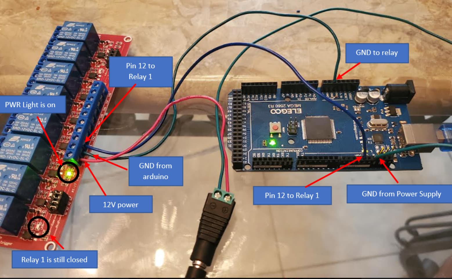
I measure 5v from pin 12 when not connected to the relay terminal, but that drops to 1.2 - 1.4v when connected to the relay terminal. I'm not sure why the voltage keeps dropping from pin 12, but no issue from 5v and 3.3v pins.

Edit: Adding Code - basically just turning on multiple pins:

#include <SD.h> // need to include the SD library
#define SD_ChipSelectPin 47 //connect pin 4 of arduino to cs pin of sd card
#include <TMRpcm.h> //Arduino library for asynchronous playback of PCM/WAV files
#include <SPI.h> //  need to include the SPI library

TMRpcm tmrpcm; // create an object for use in this sketch
int temp=1;
//int pp=5;
//int next=6;
//int prev=7;

int BlueTree1 = 13;
int BlueTree2 = 12;
int BlueTree3 = 11;
int BlueTree4 = 10;
int BlueTree5 = 9;
int BlueTree6 = 8;
int LightTree = 7;
int GreenBall1 = 6;
int GreenBall2 = 5;
int GreenBall3 = 4;
int LowIce = 3;

int MidIce = 14;
int TopIce = 17;
int CarLight = 16;
int RedBall = 15;

int CycleCounter = 0;

int delay1=1000;
int delay2=2000;
int delay3=1000;
int delay4 = 500;
int delay5 = 1000;
int rest=5000;

int pattern = 1;

void setup()
{ 
// pinMode(pp,INPUT_PULLUP);
// pinMode(next,INPUT_PULLUP);
// pinMode(prev,INPUT_PULLUP);
 
 tmrpcm.speakerPin = 46; //5,6,11 or 46 on Mega, 9 on Uno, Nano, etc
 Serial.begin(9600);
 if (!SD.begin(SD_ChipSelectPin)) // returns 1 if the card is present
 {
  Serial.println("SD fail");
  return;
 }

 tmrpcm.setVolume(5); //
 tmrpcm.play("Song1.wav"); //the sound file "song" will play each time the arduino powers up, or is reset
                          //try to provide the file name with extension

pinMode(BlueTree1, OUTPUT);
pinMode(BlueTree2, OUTPUT);
pinMode(BlueTree3, OUTPUT);
pinMode(BlueTree4, OUTPUT);
pinMode(BlueTree5, OUTPUT);
pinMode(BlueTree6, OUTPUT);
pinMode(LightTree, OUTPUT);
pinMode(GreenBall1, OUTPUT);
pinMode(GreenBall2, OUTPUT);
pinMode(GreenBall3, OUTPUT);
pinMode(LowIce, OUTPUT);

pinMode(MidIce, OUTPUT);
pinMode(TopIce, OUTPUT);
pinMode(CarLight, OUTPUT);
pinMode(RedBall, OUTPUT);
}


void loop()
{ 

Serial.println("All on");

digitalWrite(BlueTree1, HIGH);
digitalWrite(BlueTree2,HIGH);
digitalWrite(BlueTree3,HIGH);
digitalWrite(BlueTree4,HIGH);
digitalWrite(BlueTree5,HIGH);
digitalWrite(BlueTree6,HIGH);

digitalWrite(LightTree,HIGH);

digitalWrite(GreenBall1,HIGH);
digitalWrite(GreenBall2, HIGH);
digitalWrite(GreenBall3,HIGH);

digitalWrite(LowIce,HIGH);
digitalWrite(MidIce,HIGH);
digitalWrite(TopIce,HIGH);

digitalWrite(CarLight,HIGH);
digitalWrite(RedBall,HIGH);
delay(rest);
//

and the code is ?

are you sure the module expects 5V to trigger ? it seems to be a 12V trigger

you probably needed

The technical specs say
Coil Voltage 12 Volts

If you want to use this relay-board you will additionally need transistors to drive the 12V-relay-coils. With transistors that are able to switch on/off enough current so they can drive the relay-coils and you will have to add freewheeling diodes to avoid destroying the transistors.

From this comment you can see:
You should use a product that is specified exactly for the use with Arduino
You should let confirm an expert that the board you want to buy is really suitable
you should learn the basic about electronics yourself
you should NOT buy a product on amazon for two reasons
amazon is not the cheapest online-shop
even in case you have a delivery-flatrate
the technical specs provided by amazon are mostly poor and not sufficient to really check if the product is suitable

Additionally
one question on amazon is

What are the input voltage ranges for high and low (what values are considerd low and high)?

Answer:

Low is nominal 0 volts; high is either nominal 5 volts or 12 volts depending on the jumper settings.

So it might be possible to change the inputvoltage to 5V
If this is possible then the technical specs are an example of what I have written
amazon provides too poor / too less technical data

Right, the board is getting 12v from an external power supply. As I showed, the 3.3v pin is able to open the relays without an issue.

That's strange... That can happen of you draw too much current from an I/O pin but the relay board specs say 5mA trigger current and the Arduino is rated for up to 40mA (with 20mA or less recommended).

If you have a multimeter try measuring the current.

I don't see a trigger voltage spec, but you're saying it works with 3.3 or 5V.

The relay board might be defective or badly designed. :frowning: Maybe look for one from a different manufacturer.

Or maybe you can bypass the on-board relay driver and build your own. The UNL2003 comes to mind. It has 7 drivers so you'd need 2 chips for the 12 relays. It's kind-of old so there may be some newer (better?) options. It's not optically isolated but that might not be necessary and it's usually best to keep things simple, especially if you are not making your own PCB (which makes it easier to add more components).

I have used these boards before just like this, which is why I am so confused.

I used 1 arduino and 2 of these boards last year to control christmas lights with no issues.

I have tried switching to pin 13, but still the relay still does not open. The only difference is that the L light on the board turns off until the wire from pin 13 is disconnected from the relay terminal. The L light does not turn off when I try to use any other pins.

I have tried 3 different arduinos, 3 different relay boards (same model boards), and all new wires, but the behavior is the same.

Did you remember to use pinMode() to set the pins that you are using to OUTPUT?

Yes, pins are set to outputs. I measure 5v from pin 12 and 13, but that drops to 1.4v when connected to the relay terminal and the relay doesnt open.

When I use the 3.3v or 5v pins, there is no drop in voltage and the relay opens normally.

I believe this is the circuit for an input on the relay PCB, stand to be corrected.

Wire your inputs as seen below with the HIGH/LOW jumper set to LOW:


A 3V3 Arduino "MIGHT" not cut it :thinking: .


image

May be Because you were able to draw enough current from that 3.3V pin to light up the LED in the opto-isolator but when you try to draw the same current from a digital pin it just does not work and that’s also why you see the voltage drop… the voltage is then not enough to light up the LED

That does seem like the issue, the current is higher from the 3.3v (.47mA) and 5v (.84mA) pins and they work. But the current is much lower on pins 12 or 13 (.1mA) and the relay won't open.

Is there a way to fix this? I have used an arduino Mega and these relay boards before just like this, I am not sure why it wont' work this time.

Are you sure they were the same? As pointed in my Amazon link before, they exist in 5V or 12V.

Yes, using the exact same boards. I also got a replacement one just in case, same issue.

On a 2nd look, this might be your relay PCB.

Connect the board as see here with the jumpers set to HIGH trigger:

In this case the Arduino 5V output signal MIGHT not be enough for the Opto to turn on. :thinking: .

Even more confusing, when I upload code to the arduino and pin 13 is connected to the input terminal of the relay, the relay turns on 2 times before it stops working. So clearly the pin can turn on the relay, it just won't when commanded I set it to HIGH

The dedicated 5v and 3.3v pins are enough to trigger the relay, but for some reason the digital output pins are not able to even though they are reading 5v with no load.

When connected to the relay, the voltage from the digital pins drops to 1.4v, but that does not happen from the 5v and 3.3v pins.

Okay, do this test.

The trigger is set to LOW and there is a NPN transistor on the IN input of the relay PCB:

The base resistor can go to 220R.

If this circuit works the Arduino pin protection diodes are back feeding to the Arduino 5V power supply and the relay board opto never turns fully off !

That often happens if someone forgets to set the pin as an OUTPUT. It defaults to INPUT on power-up.

I just added the code to the post, I don't think it is the problem.

I already tested the code with a set of LEDs, all of the LEDs turned on with no issues.