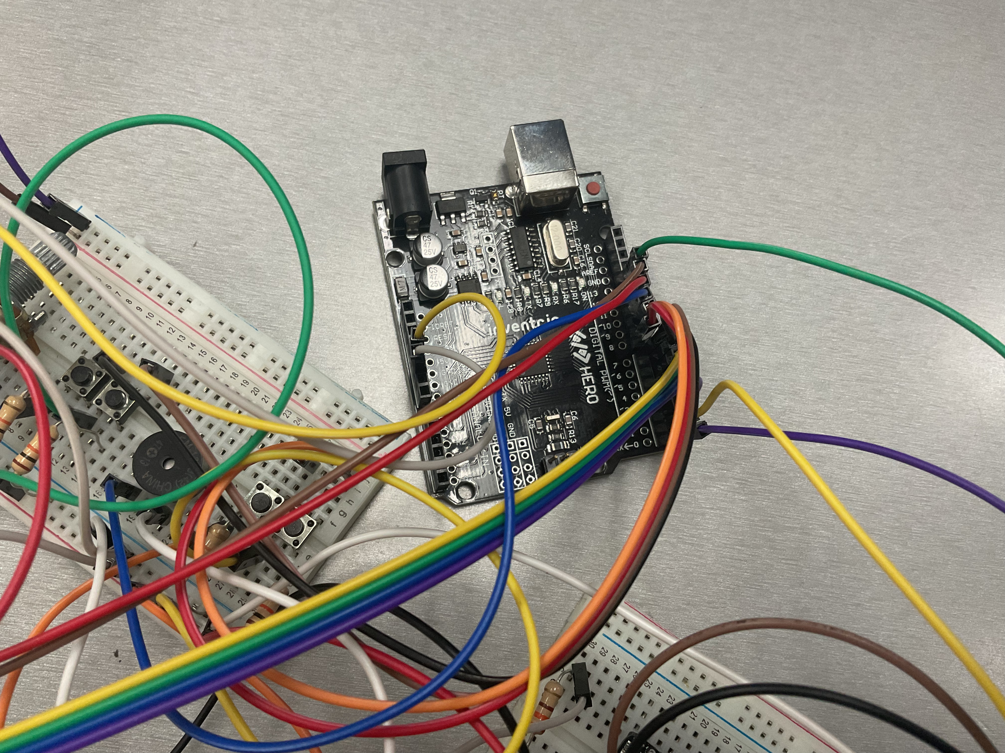
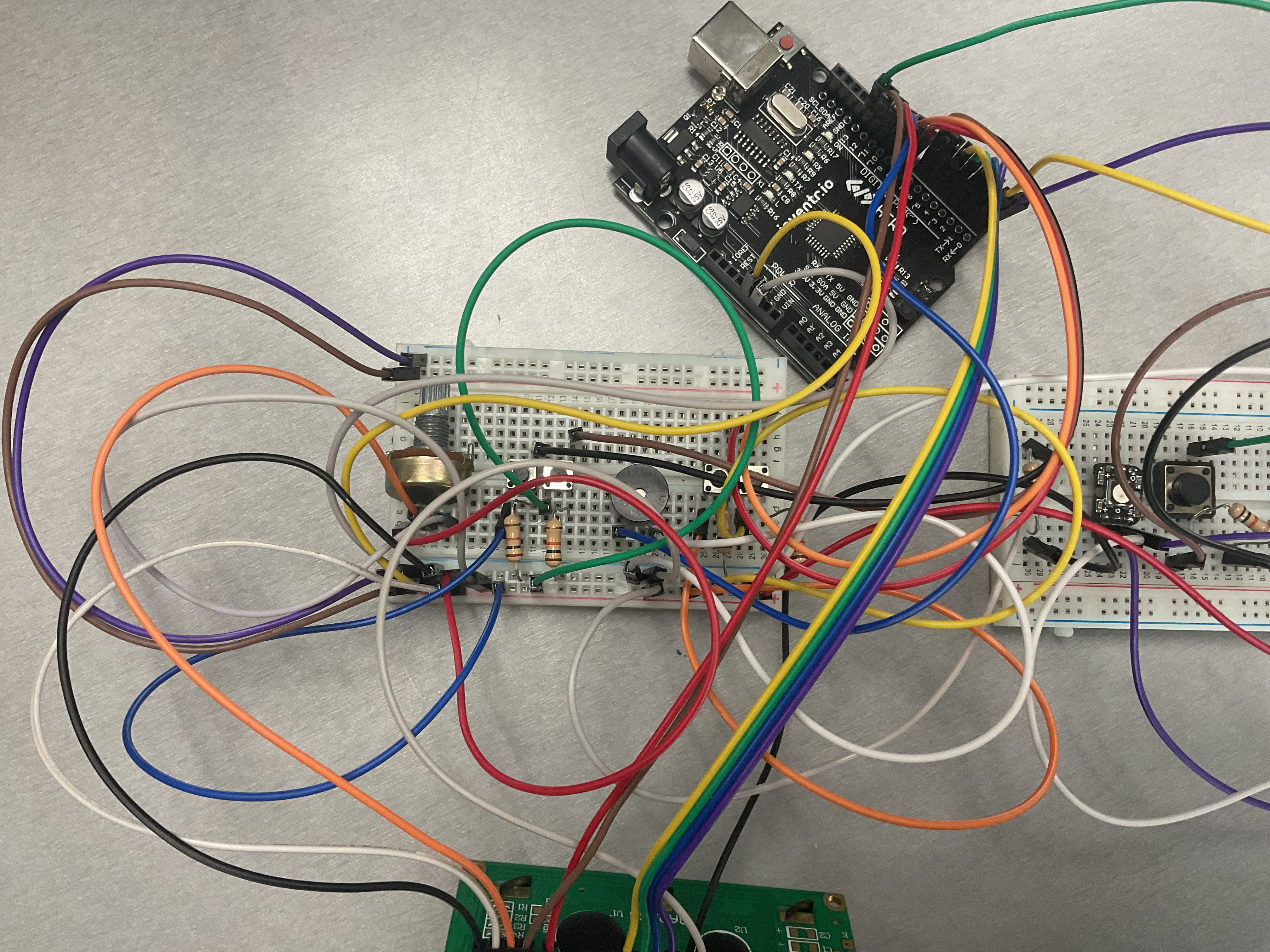
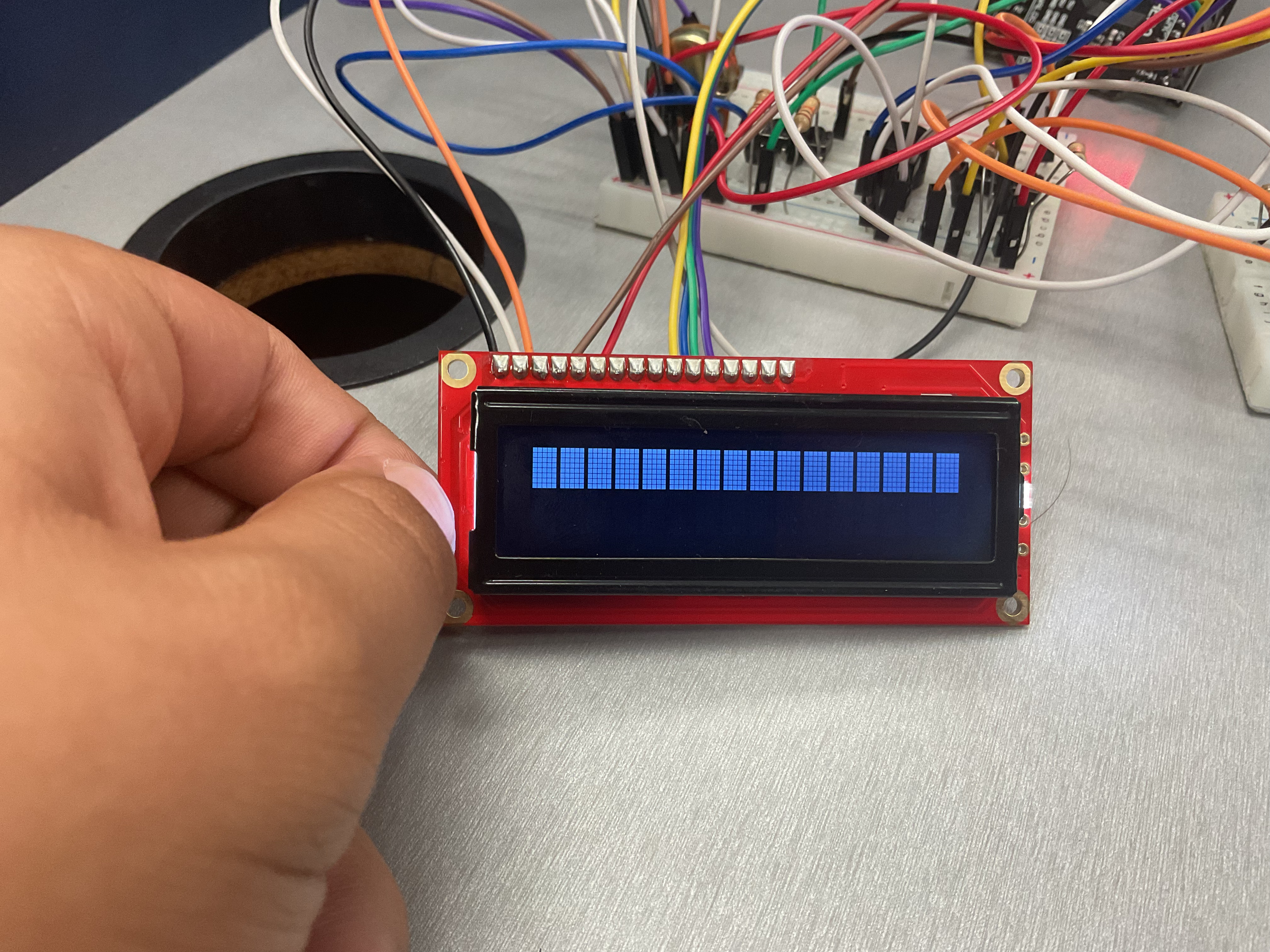
me and my friend are first year beginners, and we are trying to do a circuit from Tinkercad, (ping pong) and our LCD is not showing the setup and the functions. The rest of our physical circut functions correctly. We would appreciate your help.
*We did not write the code
also ask if you need better pics
/*

*/

// include the LiquidCrystal library
#include <LiquidCrystal.h>
LiquidCrystal lcd(12, 11, 5, 4, 3, 2);

// include the Adafruit_NeoPixel library
#include <Adafruit_NeoPixel.h>

// LED for player 1
#define neoPixel1 0
// LED for player 2
#define neoPixel2 1
#define LEDs 1

//create a NeoPixel strip1
Adafruit_NeoPixel strip1 = Adafruit_NeoPixel(LEDs, neoPixel1, NEO_GRB + NEO_KHZ800);

//create a NeoPixel strip2
Adafruit_NeoPixel strip2 = Adafruit_NeoPixel(LEDs, neoPixel2, NEO_GRB + NEO_KHZ800);

//Start, pause button
#define start 13
// Player1 up push button pin
#define P1U 6
// Player1 down push button pin
#define P1D 7
// Player2 up push button pin
#define P2U 8
// Player2 down push button pin
#define P2D 9
// piezo electric crystal pin
#define piezo 10

//paddle1
byte paddle1[16] = {0, 0, 0, 0, 0, 0, 1, 1, 1, 1, 0, 0, 0, 0, 0, 0};  // array to hold paddle1 LCD row-0&1 values
byte player11[8] = {0, 0, 0, 0, 0, 0, 1, 1};              // array to hold paddle1 LCD row-0 values
byte player12[8] = {1, 1, 0, 0, 0, 0, 0, 0};              // array to hold paddle1 LCD row-1 values

//paddle2
byte paddle2[16] = {0, 0, 0, 0, 0, 0, 16, 16, 16, 16, 0, 0, 0, 0, 0, 0};// array to hold paddle2 LCD row-0&1 values
byte player21[8] = {0, 0, 0, 0, 0, 0, 16, 16};              // array to hold paddle2 LCD row-0 values
byte player22[8] = {16, 16, 0, 0, 0, 0, 0, 0};              // array to hold paddle2 LCD row-1 values

//ball
byte ball[16] = {0, 0, 0, 0, 0, 0, 0, 1, 0, 0, 0, 0, 0, 0, 0, 0};   // array to hold ball LCD row-0&1 values
byte ball1[8] = {0, 0, 0, 0, 0, 0, 0, 1};               // array to hold ball LCD row-0 values
byte ball2[8] = {0, 0, 0, 0, 0, 0, 0, 0};               // array to hold ball LCD row-1 values

/*
  x       - cursor for ball
    bounce    - status of bounce (0 - ball moves down, 1 - ball moves up)
    direction   - direction of ball (L - left, R - right)
    v1, v2 & v3 - variables used to check whether the ball hits the paddles or not
    score1    - score of player1
    score2    - score of player2
    game    - start/stop (0 - stop, 1 - start)
*/
int x = 0, bounce = 0, v1 = 0, v2 = 0, v3 = 0;
char direction = 'L';
int score1 = 0, score2 = 0;
boolean game = 0;
int a = 0;

/*----------------------------------------setup function--------------------------------*/
void setup() {

  // initiate Neo_pixel LEDs
  strip1.begin();
  strip1.show();
  strip2.begin();
  strip2.show();

  pinMode(P1U, INPUT);      // setting push buttons as inputs
  pinMode(P1D, INPUT);
  pinMode(P2U, INPUT);
  pinMode(P2D, INPUT);
  pinMode(start, INPUT);
  pinMode(piezo, OUTPUT);   // setting piezo electric crystal as outputs

  piezoSound(50);       // piezo makes sound for 50 ms
  lcd.begin(16, 2);       // begin lcd communication
  lcd.clear();          // clear lcd screen
  lcd.setCursor(2, 0);      // set LCD cursor to (2, 0)
  lcd.print("Arduino UNO");   // print data on LCD display
  lcd.setCursor(1, 1);
  lcd.print("Ping Pong Game");
  delay(1500);

  lcd.clear();
  lcd.setCursor(0, 0);
  lcd.print("Developed by:");
  lcd.setCursor(0, 1);
  lcd.print("AIAP");
  delay(3000);
}
/*----------------------------------------end of setup function--------------------------------*/

/*----------------------------------------loop function---------------------------------------*/
void loop() {

  //executes this while loop untill start button is pressed
  while (game == 0) {
    for (a; a < 1; a++) {
      for (int i = 0; i < 16; i++) {
        if (6 <= i && i <= 9) {
          paddle1[i] = 1;
          paddle2[i] = 16;
        }

        else {
          paddle1[i] = 0;
          paddle2[i] = 0;
        }

        if (i == 7)ball[i] = 1;
        else ball[i] = 0;
      }
      x = 8;              // set ball cursor to 8
      lcd.clear();
      lcd.setCursor(3, 0);
      lcd.print("Press start");
      lcd.setCursor(3, 1);
      lcd.print("button   ->");
    }

    // check whether the start button is pressed
    if (digitalRead(start) == HIGH) {
      lcd.clear();
      lcd.setCursor(5, 0);
      lcd.print("Player");
      lcd.setCursor(0, 1);
      lcd.print("1");
      lcd.setCursor(15, 1);
      lcd.print("2");
      delay(2000);

      for (int i = 3; i > 0; i--) {
        lcd.clear();
        lcd.setCursor(4, 0);
        lcd.print("Be ready!");
        lcd.setCursor(8, 1);
        lcd.print(i);
        if (i == 1)piezoSound(100);
        delay(1000);
      }
      a = 0;
      game = 1;             // set game to 1, exits the while loop and starts the game
    }
    delay(100);
  }

  // game starts
  //when P1U is pressed, the paddle1 moves up
  if (digitalRead(P1U) == HIGH) {
    paddle1Up();
    delay(50);
  }

  //when P1D is pressed, the paddle1 moves down
  if (digitalRead(P1D) == HIGH) {
    paddle1Down();
    delay(50);
  }

  //when P2U is pressed, the paddle2 moves up
  if (digitalRead(P2U) == HIGH) {
    paddle2Up();
    delay(50);
  }

  //when P2D is pressed, the paddle2 moves down
  if (digitalRead(P2D) == HIGH) {
    paddle2Down();
    delay(50);
  }

  //split paddle1 array into 2 arrays, paddle11 and paddle12
  for (int i = 0; i <= 7; i++) {
    player11[i] = paddle1[i];
  }

  for (int i = 0, j = 8; i <= 7, j <= 15; i++, j++) {
    player12[i] = paddle1[j];
  }

  //split paddle2 array into 2 arrays, paddle21 and paddle22
  for (int i = 0; i <= 7; i++) {
    player21[i] = paddle2[i];
  }

  for (int i = 0, j = 8; i <= 7, j <= 15; i++, j++) {
    player22[i] = paddle2[j];
  }

  //split ball array into 2 arrays, ball11 and ball12
  for (int i = 0; i <= 7; i++) {
    ball1[i] = ball[i];
  }

  for (int i = 0, j = 8; i <= 7, j <= 15; i++, j++) {
    ball2[i] = ball[j];
  }

  //create custom shapes for paddle1, paddle2 and ball
  lcd.createChar(0, player11);
  lcd.createChar(1, player12);
  lcd.createChar(2, player21);
  lcd.createChar(3, player22);
  lcd.createChar(4, ball1);
  lcd.createChar(5, ball2);

  //print paddle1, paddle2 and ball
  lcd.clear();
  lcd.setCursor(0, 0);  // position of score1
  lcd.print(score1);
  lcd.setCursor(0, 1);  // position of score2
  lcd.print(score2);

  lcd.setCursor(3, 0);  // position of player11
  lcd.write(byte(0));
  lcd.setCursor(3, 1);  // position of player12
  lcd.write(byte(1));
  lcd.setCursor(15, 0); // position of player21
  lcd.write(byte(2));
  lcd.setCursor(15, 1); // position of player22
  lcd.write(byte(3));
  lcd.setCursor(x, 0);  // position of ball1, x is changed to move the ball on the display
  lcd.write(byte(4));
  lcd.setCursor(x, 1);  // position of ball2, x is changed to move the ball on the display
  lcd.write(byte(5));

  // checks whether the ball hits the paddle1
  if (x == 3) {
    for (int b = 0; b < 16; b++) {
      if (ball[b] != 0) {
        v1 = ball[b];
        v2 = paddle1[b];
      }
    }

    // if ball hits paddle1, change direction of ball to R (right)
    if (v1 == v2) {
      direction = 'R';
      score1 += 1;
      piezoSound(10);
    }

    // else display the winner
    else {
      lcd.clear();
      lcd.setCursor(3, 0);
      lcd.print("Game over");
      lcd.setCursor(4, 1);
      lcd.print("P2 won!");

      // green LED glows for winner and red for looser with piezo electric crystal sound
      for (int i = 0; i < 3; i++) {
        strip1.setPixelColor(0, 255, 0, 0);
        strip1.show();
        strip2.setPixelColor(0, 0, 255, 0);
        strip2.show();
        piezoSound(500);
        delay(500);
        strip1.setPixelColor(0, 0, 0, 0);
        strip1.show();
        strip2.setPixelColor(0, 0, 0, 0);
        strip2.show();
        delay(500);
      }

      // set scores to 0 and restart the game
      score1 = score2 = 0;
      delay(1000);
      game = 0;
    }
  }

  // checks whether the ball hits the paddle2
  if (x == 15) {
    for (int b = 0; b < 16; b++) {
      if (ball[b] != 0) {
        v1 = ball[b];
        v3 = paddle2[b];
      }
    }

    // if ball hits paddle2, change direction of ball to L (left)
    if (v1 == v3) {
      direction = 'L';
      score2 += 1;
      piezoSound(10);
    }

    // else display the winner
    else {
      lcd.clear();
      lcd.setCursor(3, 0);
      lcd.print("Game over");
      lcd.setCursor(4, 1);
      lcd.print("P1 won!");

      // green LED glows for winner and red for looser with piezo electric crystal sound
      for (int i = 0; i < 3; i++) {
        strip1.setPixelColor(0, 0, 255, 0);
        strip1.show();
        strip2.setPixelColor(0, 255, 0, 0);
        strip2.show();
        piezoSound(500);
        delay(500);
        strip1.setPixelColor(0, 0, 0, 0);
        strip1.show();
        strip2.setPixelColor(0, 0, 0, 0);
        strip2.show();
        delay(500);
      }

      // set scores to 0 and restart the game
      score1 = score2 = 0;
      delay(1000);
      game = 0;
    }
  }

  // if direction is L (left), move ball to left
  if (direction == 'L') {
    for (int b = 0; b < 16; b++)
      if (ball[b] == 16) x -= 1;

    if (bounce == 0)
      ballLeftDown();
    else
      ballLeftUp();
  }

  // if direction is R (right), move ball to right
  if (direction == 'R') {
    for (int b = 0; b < 16; b++)
      if (ball[b] == 1) x += 1;

    if (bounce == 0)
      ballRightDown();
    else
      ballRightUp();
  }
}

/*----------------------------------------end of loop function--------------------------------*/

/*-------------------------------------------other functions----------------------------------*/

//paddle1Up function
void paddle1Up() {
  if (paddle1[0] != 1) {
    int temp = paddle1[0], i;
    for (i = 0; i < 16; i++)
      paddle1[i] = paddle1[i + 1];
    paddle1[i] = temp;
  }
}

//paddle1Down function
void paddle1Down() {
  if (paddle1[15] != 1) {
    int temp = paddle1[15], i;
    for (i = 15; i > 0; i--)
      paddle1[i] = paddle1[i - 1];
    paddle1[i] = temp;
  }
}

//paddle2Up function
void paddle2Up() {
  if (paddle2[0] != 16) {
    int temp = paddle2[0], i;
    for (i = 0; i < 16; i++)
      paddle2[i] = paddle2[i + 1];
    paddle2[i] = temp;
  }
}

//paddle2Down function
void paddle2Down() {
  if (paddle2[15] != 16) {
    int temp = paddle2[15], i;
    for (i = 15; i > 0; i--)
      paddle2[i] = paddle2[i - 1];
    paddle2[i] = temp;
  }
}

//ballLeftDown function
void ballLeftDown() {

  if (ball[15] == 0) {
    int temp = ball[15], i;
    for (i = 15; i > 0; i--)
      ball[i] = ball[i - 1];
    ball[i] = temp;
    ballLeft();
  }
  else {
    bounce = 1;
    piezoSound(10);
  }
}

//ballLeftUp function
void ballLeftUp() {

  if (ball[0] == 0) {
    int temp = ball[0], i;
    for (i = 0; i < 15; i++)
      ball[i] = ball[i + 1];
    ball[i] = temp;
    ballLeft();
  }
  else {
    bounce = 0;
    piezoSound(10);
  }
}

//ballRightDown function
void ballRightDown() {

  if (ball[15] == 0) {
    int temp = ball[15], i;
    for (i = 15; i > 0; i--)
      ball[i] = ball[i - 1];
    ball[i] = temp;
    ballRight();
  }
  else {
    bounce = 1;
    piezoSound(10);
  }
}

//ballRightUp function
void ballRightUp() {

  if (ball[0] == 0) {
    int temp = ball[0], i;
    for (i = 0; i < 15; i++)
      ball[i] = ball[i + 1];
    ball[i] = temp;
    ballRight();
  }
  else {
    bounce = 0;
    piezoSound(10);
  }
}

// ballRight function
void ballRight() {
  for (int b = 0; b < 16; b++) {
    if (ball[b] != 0) {
      if (ball[b] == 16)ball[b] = 8;
      else if (ball[b] == 8) ball[b] = 4;
      else if (ball[b] == 4) ball[b] = 2;
      else if (ball[b] == 2) ball[b] = 1;
      else if (ball[b] == 1) ball[b] = 16;
    }
  }
}

// ballLeft function
void ballLeft() {
  for (int b = 0; b < 16; b++) {
    if (ball[b] != 0) {
      if (ball[b] == 1)ball[b] = 2;
      else if (ball[b] == 2) ball[b] = 4;
      else if (ball[b] == 4) ball[b] = 8;
      else if (ball[b] == 8)ball[b] = 16;
      else if (ball[b] == 16)ball[b] = 1;
    }
  }
}

//piezoSound function
void piezoSound(int d) {
  analogWrite(piezo, 20);
  delay(d);
  analogWrite(piezo, 0);
}

/*-------------------------------------------end of other functions----------------------------------*/

/*-----------------------------------------------end of program-------------------------------------*/