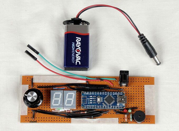
2 digit 7 segment display

Picked up my first Arduino just 2 days ago, so please bear with me, all help is greatly appreciated.

What I would like to do, is press a button, and a counter go up by 1 on each press on a 2 digit 7 segment display. After much searching, I have seen plans for 2 alternatives, a 74HC595 or a CD4511. I think they both will do pretty much the same. I also have 2, 2 digit 7 segment displays, 1 Cathode and 1 Anode. Could I please ask what the best option would be.

Probably should mention, the board I have is a Mega 2560.

Thanks :slight_smile:

Best option depends on your requirements.

At this point you probably should use parts available in making your decision.

@OP

There is one more option to run your display without a 74HC595 or a CD4511 or a MAX7219.
atemp2R.png

atemp2R.png

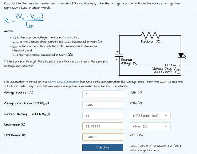
That does seem the easier option. I already had all the other parts, so think I may have been over complicating it. Could I just query the size of the resistor you suggested. You suggested 2.2k. Taking the info from the data sheet, I think it should work out to be only 100, but I may be wrong?
Output from the board 5V
Voltage drop across led 2.05V
Current 30mA
=Resistance required 100

As always, grateful for the guidance

Use 20mA per output as a safe current for the Arduino to use.

Many here find 220 Ω adequate for a single red LED.

GolamMostafa:
@OP

There is one more option to run your display without a 74HC595 or a CD4511 or a MAX7219.
atemp2R.png

Is it safe to run the common connection to an I/O pin? The current will be the sum of all the LED segment currents.

A transistor driver would be needed if the total current is > 20 mA.

david_2018:
Is it safe to run the common connection to an I/O pin? The current will be the sum of all the LED segment currents.

And that is indeed the concern. So note in that diagram, the resistors are 2k2, not 220 Ohms, limiting the total current to less than 20 mA.

And this of course, requires multiplexing code, which is a challenge in itself.

If you are serious about these displays, you use a MAX7219 and really, one of the cheaply available ready-assembled modules on eBay. Don't buy display chips (unless you want an especially large display), buy display modules - but not the ones specifying 7HC595s which are not proper display drivers.

@OP

david_2018:
Is it safe to run the common connection to an I/O pin? The current will be the sum of all the LED segment currents.

Paul__B:
And that is indeed the concern. So note in that diagram, the resistors are 2k2, not 220 Ohms, limiting the total current to less than 20 mA.

Assume that all the 8 segments are ON. Total currents to be drawn by a digit is: (5-2/2.2K)*8 ~= 11 mA which is less than the sink current (20 mA) of an IO pin of the UNO. The design looks OK; but, it is at the cost of a comfortable brightness. The cc-pin has been directly connected with an IO pin in order to avoid the use of an addition power buffer.

And this of course, requires multiplexing code, which is a challenge in itself.

Sample Example for OP
(1) Declare the following Lookup Table (LUT) to obtain cc-code for a digit (0 - 9, A - F)

byte lupTable[16] = 
{ 
0x3F, 0x06, 0x5B, 0x4F,0x66, 0x6D, 0x7D, 0x07, 
0x7F, 0x6F, 0x77, 0x7C, 0x39, 0x5E, 0x79, 0x71
}; //cc--code VS digit: 0 -----9, A ------ F

(2) Add two hex numbers:

byte x = 0x21 + 0x39 = 0x5A;

(3) Show 5 at DP0-position

[b](a)[/b]  extract 05 from 5A
byte y = x;
y = y >> 4;  //y = 05

(b) Use y as index to collect cc-code of 5 from LUT

byte z = lupTable[y]; // z = 6D the cc-code of 5

(c) Send the value of z to DP0 via PORTD

PORTD = z;

(d) Assert LL at cc0-pin and LH at cc1-pin

digitalWrite(8, LOW);
digitalWrite(9, HIGH);

(4) Follow Step-3 and show A on DP1-position of display.

(5) Now build the codes of Step-3 and Step-4 together so that 5A appears simultaneously on the display unit.

It should be said that 7-segment displays vary widely in their efficiency. Some individual displays, such as the Vishay TDSR1360-IK, are quite bright at low current values. Their reference datasheet luminance values are given at 1ma. I don't know of a 2-digit module with high-efficiency displays, but there must be some.

There's an alternate multiplexing option which would eliminate all of the segment line resistors, with just a single resistor in each CC line. You multiplex by segment instead of by digit.

The repo includes sample Nano code, and a reference in the ReadMe to a related video.

ShermanP:
There's an alternate multiplexing option which would eliminate all of the segment line resistors, with just a single resistor in each CC line. You multiplex by segment instead of by digit.

So you can use the 470 Ohm resistor.

But each segment is only on one eight of the time instead of one half of the time.

You save on resistors, but gain nothing in brightness. :grinning:

Paul__B:
So you can use the 470 Ohm resistor.

But each segment is only on one eight of the time instead of one half of the time.

You save on resistors, but gain nothing in brightness. :grinning:

Yes, I think that's right. The primary purpose was to reduce the parts count. The only way you would gain anything on brightness is if the relationship between the duty cycle and human perception of brightness is not linear. I guess that's possible, but don't know if anyone has ever studied that, and my guess is that it's roughly linear.

That said, I built a reflow controller and multiplexed the displays by segment, and got completely acceptable brightness with 2.2K resistors on the common cathode lines, which at 5V less the 1.8V LED drop is about 1.5 mA per digit if "88" is being displayed. That's using the Vishay displays, which had intensity group K ratings, which give you a lot of brightness for your milliamp.

So I think finding the right displays is pretty important. Multiplexing by segment just simplifies your life on parts and layout, at the cost of having to refresh more often, but I don't think it gives you any power savings.