The task was simple, to make custom thermometer for specific custom need and was decided to use Arduino platform. First of all big notice: check existing libraries for modules and troubleshooting before you make decision to buy them, if you expect fast and simple solution.
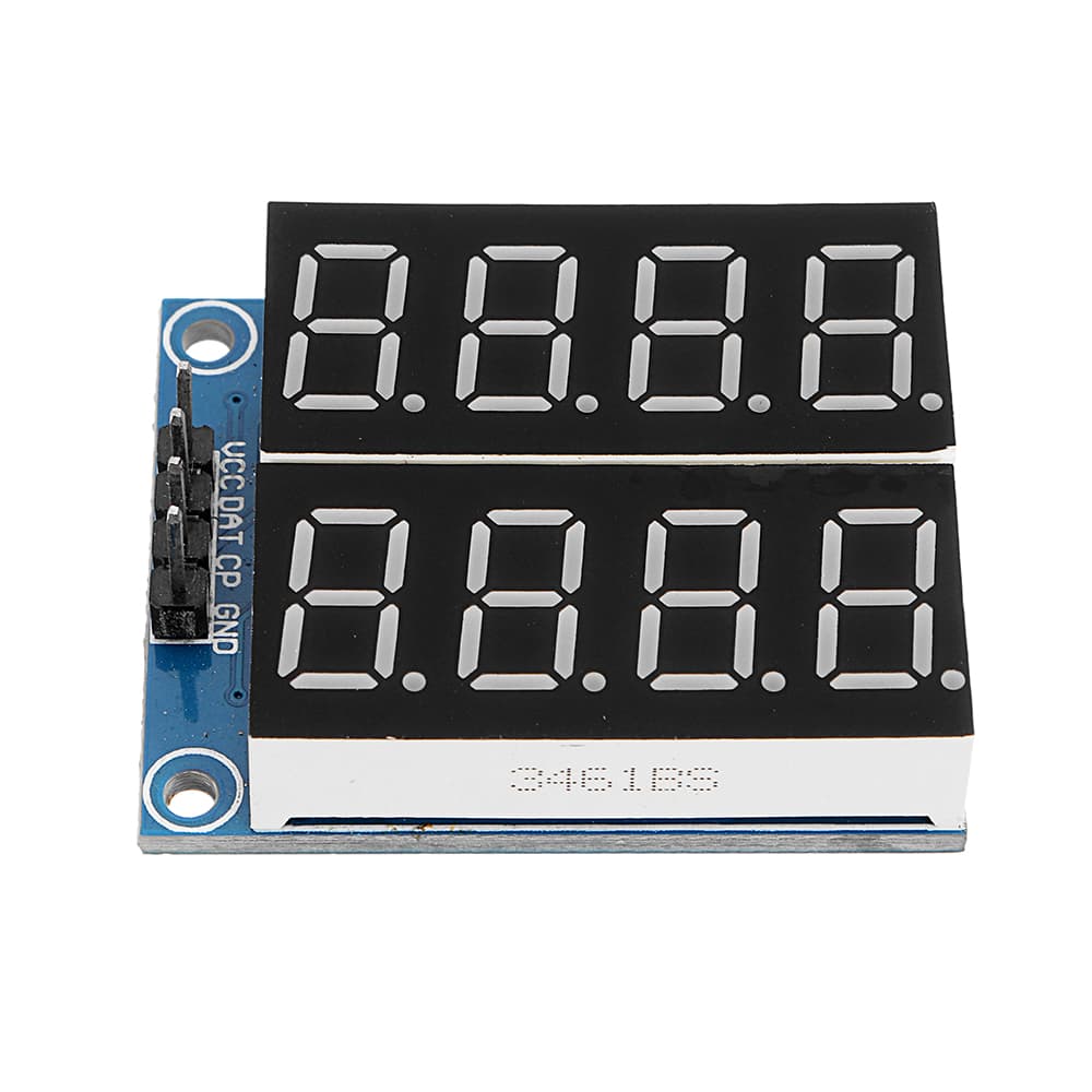
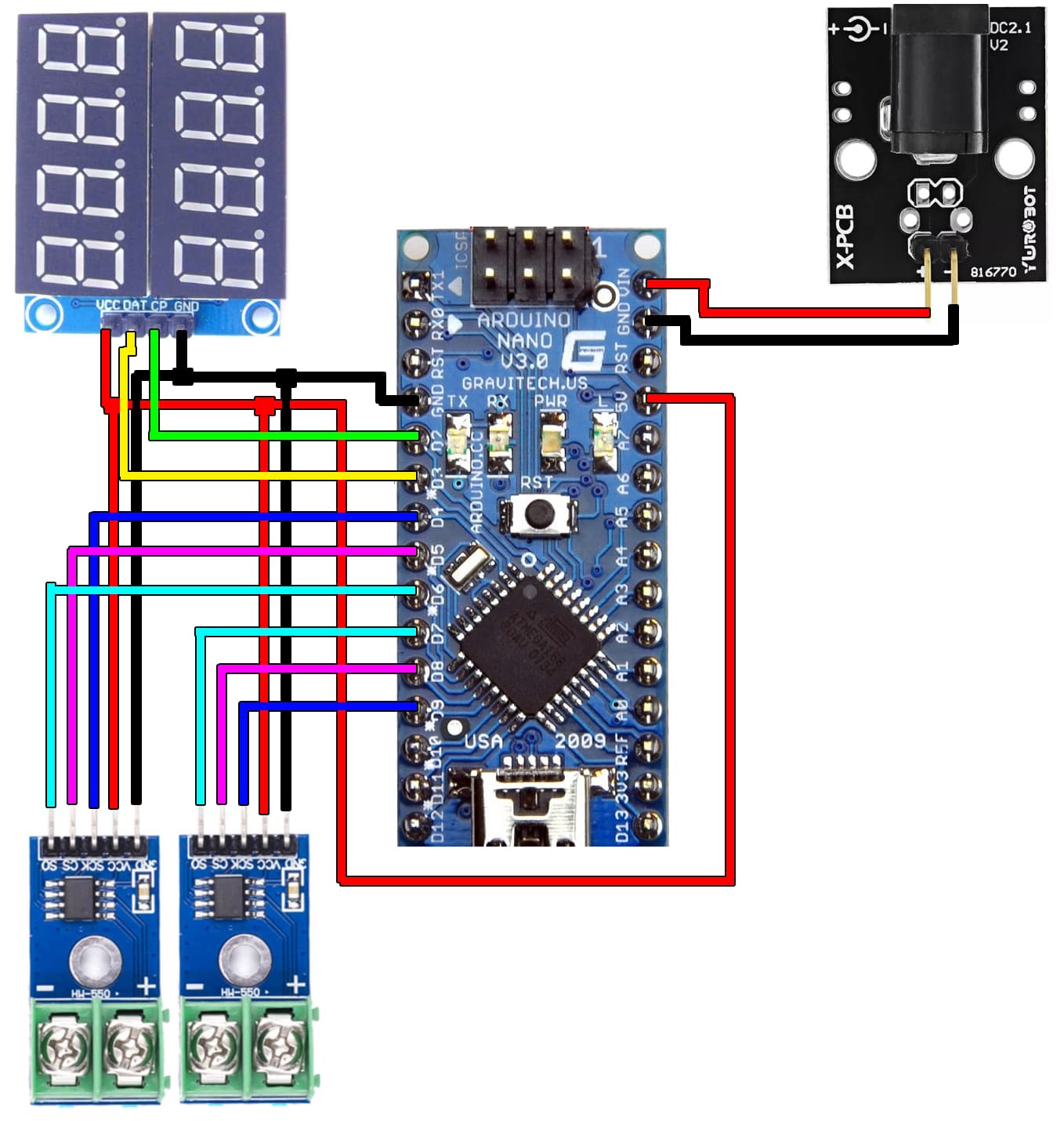
As it is said, I used 2 MAX6675 modules sold included with 2 K-type thermocouples, the HC164 LED 7-segment 8-digt display, visually divided in two rows of 4 digits, controlled with Arduino Nano V3 ATmega 328, powering it up with 5V 1A power unit via DC2.1 Module.
HC164 display
MAX6675 with chromel-alumel thermocouple

Arduino Nano

Power Unit

DC2.1 Module

I will provide you with self explanatory schematics and sketch code, but beforehand I have to say about requirements. I used custom .cpp and .h files, to which author refers as not real libraries, so I will call it "library". So there are great person, who undertook creating "library" to use with most common Arduino displays Display driver for LCD displays on Arduino
He gives specific instructions on how to use it, with specific display. I will provide you with edited files specifically for HC164, so if parameters doesn't suffice, feel free to visit this magnificent website. I will only say that I had to directly contact developer with troubleshooting, because as it seemed HC164 required to use DISPLAY_INTR(display); function in the code to start working, and not just changing parameters in .h file, as I thought reading manual for the "library".
You have to understand that it is one 8 Digit display, and it is up to us to interprete it as 2 row 4 digit display. I want to display one temperature in one row, and such LED is visually more suitable for that, but we work with it as just one big line of digits. So I set up first 4 digits for the first temperature, and last 4 digits for the second.
Also in case of MAX6675 module naughty behaviour, you messing up contacts or just uncredited behaviour, you will read temperature value as "nan", and if you pass it as a float to the LED display it breaks it, and you have to restart your arduino through power down. I made it so if you recieve nan value, you send a "nan" as text to the display and it works.
With temperatures over 100, it can display only 1 digit after float point, and I made conditions, at which display shows 2 digits after float point at values lower than 100 and 1 digit at values higher than 100. I am not going to work with temperatures higher than 1000 so It is up to you to add condition for that. Without these conditions display messes up values, so you can't just pass any float value and expect it to fit it into 4 digits.
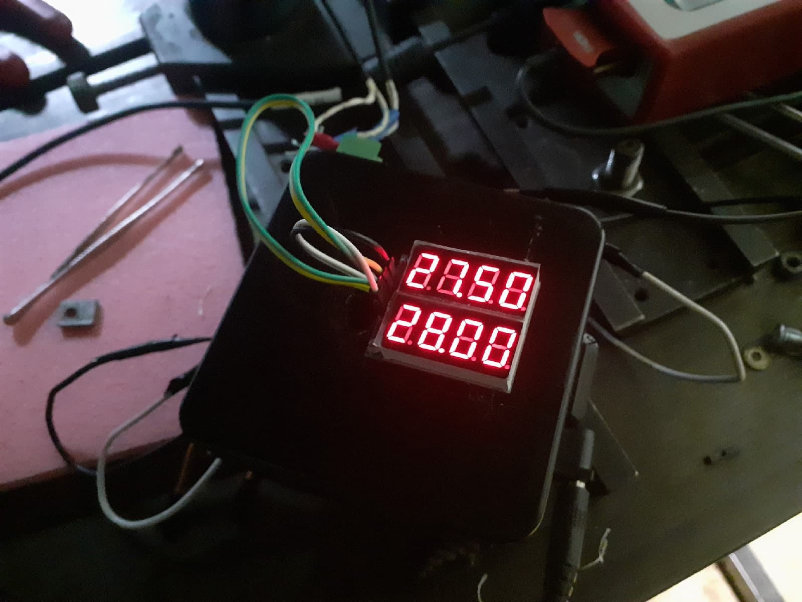
Here are images of pre final result, since I am aware that it looks a lot like orcish technologies, and due to some reasons, which I will unravel at the end, I will make it look much better, but in other project. Anyway it is working and not flickering.
Also you'll have to have max6675.h library.
Here are the schematics.
Here is the code for the passers by, if you don't want to download anything
// here we import code in the same folder as the sketch
#include "LEDDisplayDriver.h"
// here we import library
#include <max6675.h>

// Made so if you messed up with LEDDisplayDriver.h file, program will not let you run it
#ifndef _HC164_
#error "_HC164_ must be defined in LEDDisplayDriver.h for this sketch to work"
#endif

//*************************************************************************
// Define the pins used for the display connection. I use digital pins.
#define DAT_PIN 3
#define CP_PIN 2

// Define separeate variables for two different values of different temperatures.
float Tup;
float Tdwn;

// Define the pins used for the 1-st MAX6675 connection. I use digital pins.
int TCupSO = 6;
int TCupCS = 5;
int TCupSck = 4;

// Initialise 1-st MAX6675 module.
MAX6675 Module_up(TCupSck, TCupCS, TCupSO);

// Define the pins used for the 2-nd MAX6675 connection. I use digital pins here as well.
int TCdwnSO = 7;
int TCdwnCS = 8;
int TCdwnSck = 9;

// Initialise 2-nd MAX6675 module.
MAX6675 Module_dwn(TCdwnSck, TCdwnCS, TCdwnSO);

// Initialise LED display.
LEDDisplayDriver display(DAT_PIN, CP_PIN, true, 8);

// This function is needed because display requires interrupts to work.
// Without it Display will not work at all.
DISPLAY_INTR(display);

void setup() {
  // put your setup code here, to run once:
  // you can use it for troubleshooting to read temperature via serial port
  // and see values in the serial monitor
  Serial.begin(9600);// initialize serial monitor with 9600 baud
}

void loop() {
  // put your main code here, to run repeatedly:
  // Read values in variables once, so that you don't have to overload
  // controller reading temperature every time you need it's value
  Tup = Module_up.readCelsius();
  Tdwn = Module_dwn.readCelsius();

  // for troubleshooting you can use it to dipslay read temperature via serial
  //Serial.print("C_up = ");
  //Serial.println(Tup);
  //Serial.print("C_dwn = ");
  //Serial.println(Tdwn);

  // Since values I read are form 2 modules and LED have 2 rows of 4 digts,
  // I am interested in interpreting each row as separate temperature, so
  // with temperatures over 100, it can display only 1 digit after
  // float point, and I made conditions, at which display shows
  // 2 digits after float point at values lower than 100 and 1
  // digit at values higher than 100.
  // I am not going to work with temperatures higher than 1000 so
  // It is up to you to add condition for that.

  // Since it is interpreted as 8 digits display, you have to
  // separate rows addresing 1-4 digits as for the first row
  // and 5-8 for the second row. (remember 4 doesnt count and count starts from 0 - display.showText("nan",0,4);)

  // Also, if you have bad connection or your temperature module
  // is behaving naughty, you will get nan value, and it breaks
  // LED display, if you will try to pass it as a float. So
  // in case of nan value, I jsut pass to the display "nan" text.
  if (isnan(Tup)){
    display.showText("nan",0,4);
                                     }
  else{

    if (Tup >= 100){
    display.showNum1decimal(Tup, 0, 4);
                  }
    else {
    display.showNum2decimals(Tup, 0, 4);
        }
     }
  if (isnan(Tdwn)){
    display.showText("nan",4,8);
                                     }
  else {

    if (Tdwn >= 100){
    display.showNum1decimal(Tdwn, 4, 8);
                    }
    else {
    display.showNum2decimals(Tdwn, 4, 8);
        }
      }

  delay(200);

}
Thermometer_HC164LED_MAX6675.zip (31.2 КБ)
p.s. After finishing the device, It became clear, that precision isn't sufficient. MAX6675 is a 12-bit resolution module meaning that display will show temperature with step of 0.25°C. It means that if you measure temperature between 27°C and 28°C, all possible values are just 27.00, 27.25, 27.50, 27.75 and 28.00. To count that the simple way you can divide your Thermocouple max temperature by 2 in power of bits, in my case it is 1024/2^16 = 1024/4096 and you get 0.25. So I now I need to undertake another project replacing MAX6675 with ADS1118, which is 16-bit module, therefore in theory I'll get 0.016°C step which is sufficient enough. But more on this in another project, so until then, have a good one, and I hope I helped you in some way.