20MHz Atmega328P in custom board with Optiboot not accepting sketch with avrdude

Greetings -

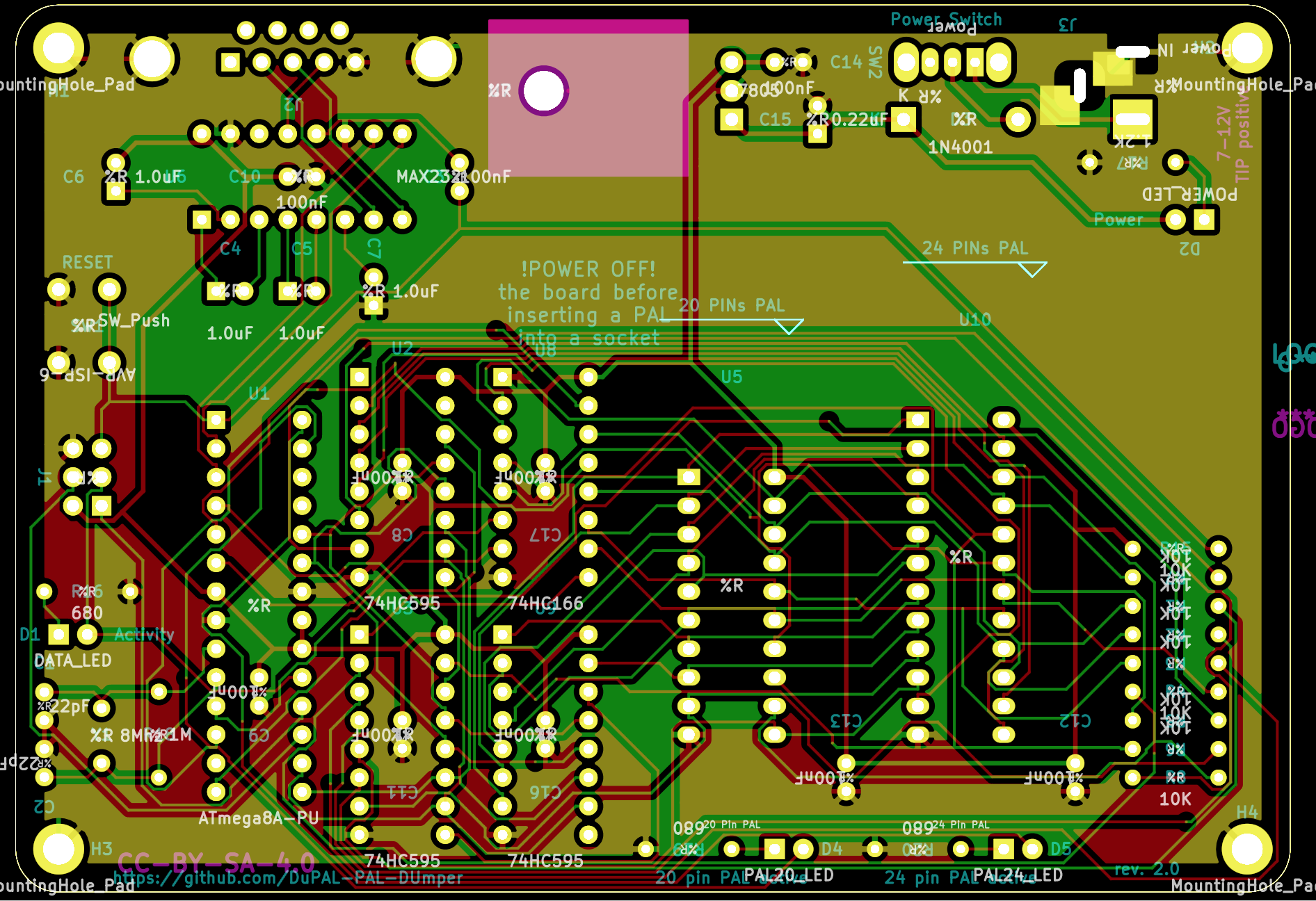
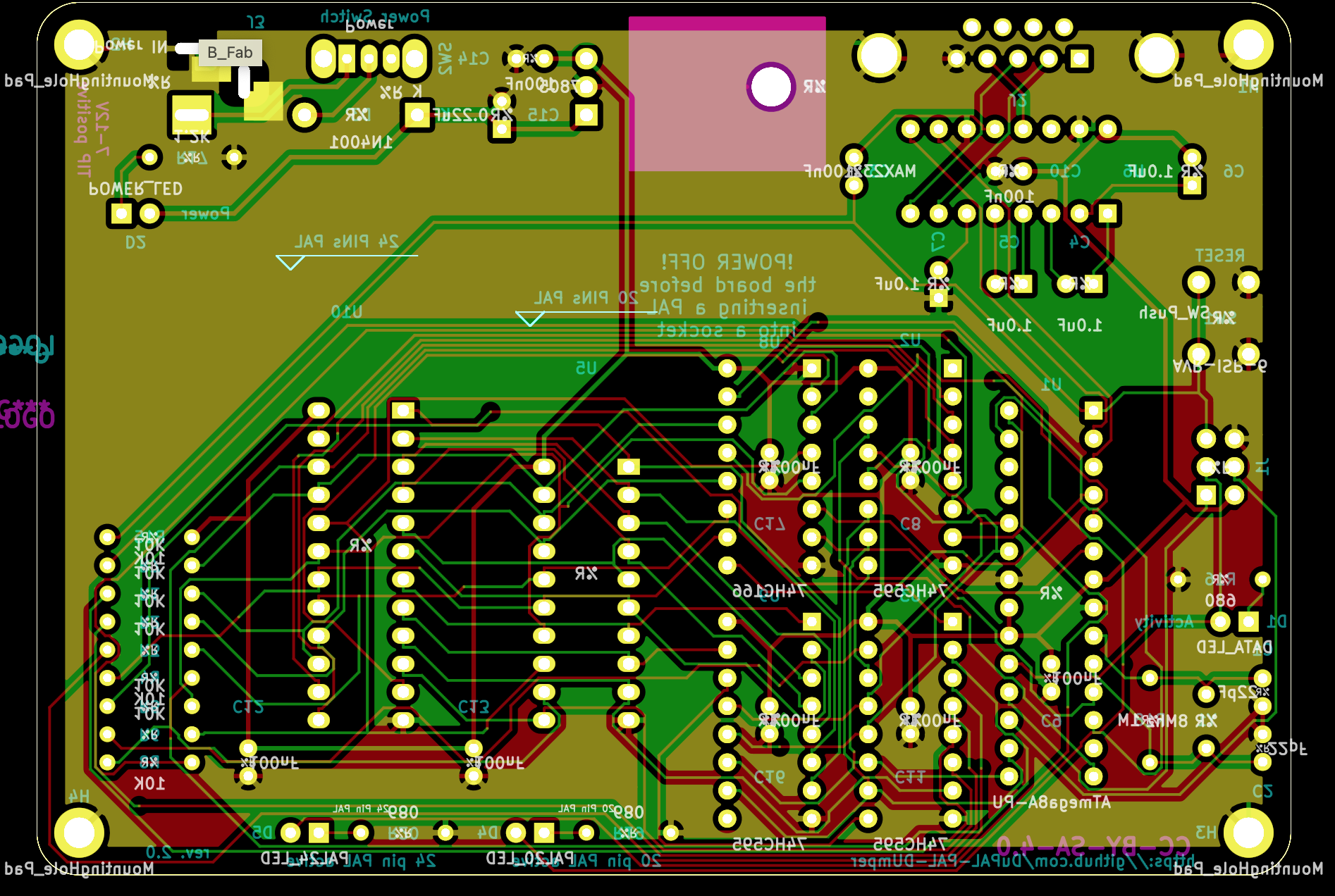
I've built one of these projects, which uses a Atmega328P clocked at 20MHz. (It uses the standard two 22pF caps on the external 20MHz oscillator.) Here's a picture of a finished unit (not mine.)

When building Optiboot, I'm building it for 20MHz at 56000bps, per the guide -

make atmega328 AVR_FREQ=20000000L LED_START_FLASHES=8 BAUD_RATE=57600

After installing the bootloader to the Atmega328P (I verified with a my Dataman 48Pro2 that the boot loader starts at >3F00, and has fuses >FD, >DE, and >FF set.) The board does boot and the LED on it flashes eight times in a loop, just like I compiled it to do. This tells me the apparently the boot loader is running OK.

It should now be waiting for a sketch to be loaded on its serial port at 57600bps, which in this board's case is behind a MAX232 IC and some capacitors, and has a DB9 standard serial port (so I can use a regular DB9 to USB adapter.)

This is where things go strange. I've tried several different USB to serial adapters, and even tried both Windows and Mac, but I keep getting essentially this same thing when running avrdude:

avrdude -p m328p -P /dev/tty.usbserial-1420 -c arduino -B2 -b 57600    -U flash:w:out/DuPAL.hex  
avrdude: stk500_recv(): programmer is not responding
avrdude: stk500_getsync() attempt 1 of 10: not in sync: resp=0x00
avrdude: stk500_recv(): programmer is not responding
avrdude: stk500_getsync() attempt 2 of 10: not in sync: resp=0x00
(etc)

That tells me there is a communication issue between avrdude and the Atmega328P - but there's not much between them that I haven't swapped out. The USB to serial cable works on other devices (both in Windows and Mac), and I've tried multiple. I've swapped out the MAX232 several times just to eliminate it. And the boot loader appears to be working because it's blinking the LED eight times. It's just not allowing serial transfer.

Any thoughts as to things I can eliminate here or look at? Are there any other caveats that running this thing at 20MHz caused with regards to the baud rate? Or, should I maybe try slowing the crystal down to a 16MHz one and recompiling Optiboot?

Thanks!

Please post the schematic. From the brief description, you are missing essential components, like power supply decoupling capacitors.

Hi, @jremington -

The Gerber and .sch files are in the Git repo that I posted above from the original KiCAD project. Take a look in the DuPAL-PAL-DUmper/DuPAL_Board/tree/master/board/DuPal_DIP directory.

The best I can do without loading KiCAD is this online viewer of both sides of the PCB:


The BOM at the bottom of the main project page as well.

The MAX232 does have five capacitors nearby - and then those traces go to the Atmega 328's serial pins and the DB9. The 20Mhz crystal and 22pF caps connected to the Atmega 328 follow the recommended external crystal circuit in section 8-2 of the Atmega 328 manual. Those are really the only things that should be impacting the programming of the AVR, but I'm here to listen to any other advice that I can get :slight_smile:

Sorry for only two URLs - the system won't let me put more than two.

Also, a side note - this isn't my project - it's someone else's, but they supposedly have it working, and others have it working too. So, I must be doing something differently.

Thanks!

You should not expect forum members to go off site to dig up the data on your project.

If you want help, follow the forum rules and post an image of the circuit schematic in line, not Gerber or .sch files. The board layouts are neither interesting nor useful.

If "others" have successfully built the gizmo, compare notes with them to see what you did wrong.

I'll try and hand-draw the section of the schematic where the Atmega 328P is, including the MAX232 circuitry, and post it here. Please give me a few days. Hopefully that will help. Thank you, @jremington!

Hi, @hexbus

You should be able to EXPORT a jpg or png schematic image from your CAD.

Tom.. :smiley: :+1: :coffee: :australia:

Don't be silly, as you are likely to make mistakes and/or leave out critical details. Export the entire schematic as a pdf or high resolution image file (as suggested above) and post that.

Your very best bet for advice is from people who have actually built this!

Hey all -

@jremington - Hand draw = I was going to use something like draw.io or another tool. I'd also normally contact the person who authored it (or if I could find a community who actually used these, I'd go there), but the author has a rather terse "go away" (for lack of a better word) on their Git repo. It's hard to figure out how to troubleshoot without asking others for help somewhere :slight_smile:

I did realize that there was an actual schematic in their repo, and after digging, determined it was a KiCAD schematic. So, I did get KiCAD loaded and spent the past hour learning how to fix missing component symbols on the original schematic from the repo, exported it as a PDF, and then placed it in my Git repo:

This looks pretty accurate from what I see on the board. The only difference is that the schematic mentions an 8A vs. the 328P that is mentioned on the Git repo to actually install on the board. These are pin compatible, and I only assume they upgraded to the 328P because it was necessary.

The pictures of the board coupled with the schematic hopefully can help a bit now.

Thank you for your patience with me.

Please pay attention. Post the schematic inline, right in your next post, as requested.

Please explain; you could be a little nicer and helpful on that front. The forum software here does not allow me to upload files inline (I don't have permission, it states). That appears to be the only widget that allows me to manipulate files here besides providing a direct link.

Neither is there an apparent "help" function that I can find anywhere for this forum software to find alternate ways. (I've searched on Google and the "Search Forum" box.)

I realize that everyone here is another user just like me, and really - all I want to do is participate and follow the rules, but I have to know what they are. I understand that there are certain expectations for users here; I've already read the community guidelines (that was the only thing presented to me). Groups can go far by helping point new users in the right direction so that they can be productive from the get-go and not have to guess about etiquette.

This is as professionally prepared schematic, and quite standard, but the crystal is specified as 8 MHz.

Original PDF (higher resolution) attached below.
dupal schematic.pdf (235.5 KB)

Apparently, at a frequency of 20Mhz and a set speed of 57600, the error level is not provided.
The author offers only three speeds.

optiboot

Wow. Over 100 different ATmega328 bootloaders in minicore, and you picked one that isn't included! (not that the values are unreasonable... Just unlucky.)

Here's an Optiboot compiled for 20MHz and 57600...
(rename to .hex before attempting to burn.)
optiboot_flash_atmega328p_UART0_57600_20000000L_B5.hex.txt (1.4 KB)

the author of miniCore clearly and unequivocally showed that for 20Mhz quartz, the speed of 57600 is beyond good

Huh? That just shows that it isn't included in minicore.
It should work fine:

optiboot>make atmega328 AVR_FREQ=20000000 BAUD_RATE=57600
avr-gcc (AVR_8_bit_GNU_Toolchain_3.6.2_1778) 5.4.0
Copyright (C) 2015 Free Software Foundation, Inc.
This is free software; see the source for copying conditions.  There is NO
warranty; not even for MERCHANTABILITY or FITNESS FOR A PARTICULAR PURPOSE.

BAUD RATE CHECK: Desired: 57600, Real: 58139, UBRRL = 42, Difference=0.9%
avr-gcc -g -Wall -Os -fno-split-wide-types -mrelax -mmcu=atmega328p -DF_CPU=20000000  -DBAUD_RATE=57600 -DLED_START_FLASHES=3                 -c -o optiboot.o optiboot.c
avr-gcc -g -Wall -Os -fno-split-wide-types -mrelax -mmcu=atmega328p -DF_CPU=20000000  -DBAUD_RATE=57600 -DLED_START_FLASHES=3               -Wl,-Tlink_optiboot.ld -Wl,--relax -nostartfiles -o optiboot_atmega328.elf optiboot.o
avr-size optiboot_atmega328.elf
   text    data     bss     dec     hex filename
    474       0       0     474     1da optiboot_atmega328.elf
avr-objcopy -j .text -j .data -j .version --set-section-flags .version=alloc,load -O ihex optiboot_atmega328.elf optiboot_atmega328.hex

Yes, 0.9% is sufficient accuracy!
Can you compile for 115200, see what accuracy is there?

optiboot>make atmega328 AVR_FREQ=20000000 BAUD_RATE=115200
avr-gcc (AVR_8_bit_GNU_Toolchain_3.6.2_1778) 5.4.0
Copyright (C) 2015 Free Software Foundation, Inc.

BAUD RATE CHECK: Desired: 115200, Real: 113636, UBRRL = 21, Difference=-1.3%

Still good enough.
(115200@16MHz is 2.1% off. But then, in an Uno, it's paired up with another UART of the same type with the same configuration.)

Hey, everyone!

After #include <dayjob.h> today, I did some more troubleshooting.

  1. I took the 20MHz crystal out and put a 16MHz crystal in, so that I could throw a plain vanilla Adafruit 328P in (new in package, with boot loader) to get to a consistent state. (This is one of her older ones that still operated at 9600 baud and blinks the LED on boot to let you know its working.)
  2. The Adafruit 328P did fire up in the DuPAL board and did blink the LED as expected.
  3. I temporarily moved the Adafruit 328P to an Arduino Uno and wrote a sketch to it that sent an ASCII chart in a loop out of the console at 9600 baud. Then placed it back in the DuPAL board. Powered it up, and observed no serial output from the board at 9600.
  4. I removed the MAX232 on the DuPAL and also tried two others ones that I have. These are all labeled TI MAX232 ICs. Nada - no output.
    4A) Tried three USB to serial adapters. Tried my built in COM1 port on my Dell 5060 desktop. Nope.
    4B) I used a multimeter and compared the MAX232 pinout (and attached capacitor pinout) to not only the schematic, but also several reference documents from MAX232 data sheets. I also used my magnifier screen to verify my capacitor values, and double checked all my solder connections.
  5. I took one of these inexpensive DE9 to 4 pin adapters (has a SMT MAX3232 on it with a 4 pin header) and hooked it up with jumpers to the pins on the empty MAX232 socket (I believe it hooks to pins 9, 10, 15, and 16 for RX/TX/GND/VCC). This has the effect of hooking directly to the Atmega328P’s serial lines. Powered up the DuPAL - bingo. Have serial output at 9600. Prints and loops correctly.

Here’s where I need to probably go from here:

  1. I ordered ten new MAX232’s from a leading electronics site (so that I know that they’re genuine.) I must have gotten a bad batch of these last time, and I have no recollection of where I got them.
  2. When I get the new MAX232 in, if it solves my problem, great! I’ll try to program it at 16MHz over serial and if that works, I’ll then change the crystal back to 20MHz and try to recompile and burn the 20MHz Optiboot all over again, and then try to program over serial.
  3. If I have problems with the new MAX232, I’ll revisit this thread again.

Thanks for the feedback on some of the schematic errors, too. I’m guessing the open source author did not correct a few things on their schematic document when they committed new versions of the project to their repo. (I.e. this looks like it started with an Atmega8 and an 8MHz crystal, and ended up with an Atmega328P and a 20MHz crystal.). I’ll fix the issues and offer them a merge request and see if they accept.

I’ll post an update once I get the MAX232 IC’s in and see if I can get serial output working. crossing fingers. I appreciate everyone being patient with me, as it sometimes takes me a while to convey information correctly. Autism is a challenge in of itself, and is a constant learning experience.

And what do we want ... if there are UNO clones in that fake one ... let's take a little more air .... CH-340 )))

This topic was automatically closed 180 days after the last reply. New replies are no longer allowed.