I'm pretty new here, I just would like to ask, since this question did not seem to appear anywhere in Google.
So, actually I got a project which requires: water flow sensor and a solenoid valve and I would like to control it using arduino uno and a shield also displaying it in an LCD. Everything works well, until at a point where controlling solenoid valve is all good, however the valve and the 220VAC is messing with my flow reading, which is pretty annoying. Could anybody give me a solution to this?
Thank you very much.
additional information: So I would like to see the water flowing and display it unto the LCD. For example, if the total flow reaches 800mL, it would deactivate the relay and thus close the valve. That is my basic thinking on this. Thank you. Also simple schematics are in the attachment.
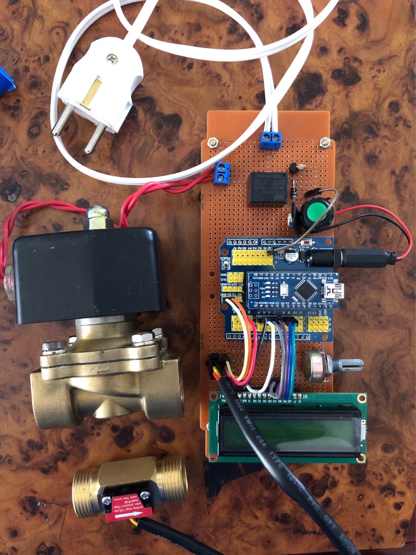
p.s: I've added new "block diagram" and my PCB currently. I have not inserted any pipe, but am just trying to blow some air through the flow sensor.
Your block diagram (not a schematic) show a box labeled 9v. Is this also powering the Arduino? If so, the operation of the relay is what is affecting the Arduino, not the 220 VAC.
It's not clear what conditions exist when the flow sensor is being "messed with".
In theory, the solenoid coil is only going to cause noise when it is opening or closing. At this time the flow meter will go from 0 to something, or something to 0. Would thing the "messing" would be masked by the on to off.
If the 220VAC being on is messing with the flow it would be likely a layout issue.
Please describe what and when the flow meter is being affected.
JohnRob:
It's not clear what conditions exist when the flow sensor is being "messed with".
In theory, the solenoid coil is only going to cause noise when it is opening or closing. At this time the flow meter will go from 0 to something, or something to 0. Would thing the "messing" would be masked by the on to off.
If the 220VAC being on is messing with the flow it would be likely a layout issue.
Please describe what and when the flow meter is being affected.
John
So I've changed my schematics / block diagram picture, and here it is all compacted in one PCB. So the problem here is that first i powered the Arduino and relay using the same 9V battery. I programmed the arduino to show the data in my LCD of my total flow from the inlet. However, when i connect the 220VAC into the socket, it somehow change the total flow in my LCD into random numbers, even I have not put any liquid flow through my sensor. Thank you for all your replies. I'll try to explain it the best I could. Thank you.
A common 9volt smoke alarm battery is very weak (low current capacity).
It might be able to power an Uno for a while.
It will be struggling with the extra current of the LCD backlight.
And could collapse under the added current of your (unspecified) relay.
Solenoid valves create a high voltage spike when turned off.
That high voltage spike could upset code execution of the Arduino, resulting in all sorts of weird things.
That kickback spike needs to be killed, either with a MOV or snubber circuit.
Leo..
Ignore the LCD and use debug printsto verify
that the LCD is the ONLY component affected and everything works EXCEPT the LCD.
This ("AC switching corrupts LCD display ") is
a common issue we have seen a hundredtimes.
The only way to prevent it is to add a ton of electrolytic filter caps onthe LCD 5V power pin as well as a bunch of 0.1uF decoupling caps on the
same line. Don't bother posting any more on this issue until that's done. You'll need at least 1000uF
on the LCD 5V pin. Ignore the LCD until you've
done that. Focus on verifying your system actually
works correctly ( if you don't look at the LCD)
Okay, for now maybe looking at one way I would like to move my relays and other connectors on other PCB just to isolate the spikes of AC on DC and things like that. I'll update more on this forum. Thank you very much on your help, guys!
Trust me. Everything works.
Look at your debug printouts.
If you ignore the LCD you'll see theres nothing wrong with your circuit.
Here's a couple of suggestions from the old arduino posts on the same problem:
I think I got it! A friend suggested to put diodes on every connection going back to the arduino and it worked haha. I used the same diodes that were used in the relay box.
To all that have weird characters on LCD screen when you run 117 Volts from a relay using the Arduino!
This is what I found. Put a 470 uf electric capacitor across the SIGNAL pin on the relay and ground. That fixed all the issues for me.
I driving the relay with a separate power supply, which didn't work which led me to believe It could be the signal pin and sure enough it was. Hope this works for everyone else having the same issue.
1/11/2018