3.5" SPI LCD touch screen ili9488

Hi.

In the adafruit library, in begin() start writecommand with 0xEF, but in the datasheet of ILI9486, 0xEF don't exist.

For example, in datasheet say

B0h IFMODE (Interface Mode Control) 
                   D/CX RDX WRX    D[15:8]     D7     D6   D5   D4    D3    D2     D1   D0   HEX 
Command         0     1      ↑   XXXXXXXX     1      0     1     1     0     0      0     0    B0h 
1st Parameter   1     1      ↑   XXXXXXXX SDA_EN    0      0      0    VSPL  HSPL  DPL   EPL   XX 
Description 
Sets the operation status of the display interface. The setting becomes effective as soon as the command is received. 
EPL: DE polarity (“0”= High enable for RGB interface, “1”=Low enable for RGB interface) 
DPL: PCLK polarity set (“0”=data fetched at the rising time, “1”=data fetched at the falling time) 
HSPL: HSYNC polarity (“0”=Low level sync clock, “1”=High level sync clock) 
VSPL: VSYNC polarity (“0”= Low level sync clock, “1”= High level sync clock)  
SDA_EN: 3/4 wire serial interface selection 
SDA_EN = “0”, DIN and DOUT pins are used for 3/4 wire serial interface. 
SDA_EN = “1”, DIN/SDA pin is used for 3/4 wire serial interface and DOUT pin is not used.

I understand that in my case, I need send parameter b0(sda_en'0')0000(VSPL)0(HSPL)0(DPL)0(EPL) is b0000000 or 0x00, true???

I go in good line?

Hi, I try with this code into begin library, but the screen don't work, it change beteen various grays tone.

if (hwSPI) spi_begin();
		writecommand(0xB0); // Interface Mode Control
		writedata(0x00);
		writecommand(0x11);
		delay(250);
		
		writecommand(0x3A); // Interface Pixel Format
		writedata(0x55);
		
		writecommand(0xC0); // Power Control 1
		writedata(0x0A);
		writedata(0x0A);
		
		writecommand(0xC1);
		writedata(0x45);
		writedata(0x07);

		writecommand(0xC2); // Power Control 3
		writedata(0x33);
		
		writecommand(0xC5); // VCOM Control
		writedata(0x00);
		writedata(0x42);
		writedata(0x80);
		writedata(0x00);
		
		writecommand(0xB1); // Frame Rate Control
		writedata(0xD0);
		writedata(0x11);
		
		writecommand(0xB4); // Display Inversion Control
		writedata(0x02);
		
		writecommand(0xB6); // Display Function Control
		writedata(0x00);
		writedata(0x02);
		writedata(0x3B);
		
		writecommand(0xB7);  // Entry Mode Set
		writedata(0x07);
		
		writecommand(0x36);  // Memory Access Control
		writedata(0x2B);
		
		writecommand(0xB3); // FrameRate Control
		writedata(0x00);
		
		writecommand(0xE0); // PGAMCTRL(Positive Gamma Control)
		writedata(0x0F);
		writedata(0x1F);
		writedata(0x1C);
		writedata(0x0C);
		writedata(0x0F);
		writedata(0x08);
		writedata(0x48);
		writedata(0x98);
		writedata(0x37);
		writedata(0x0A);
		writedata(0x13);
		writedata(0x04);
		writedata(0x11);
		writedata(0x0D);
		writedata(0x00);
		
		writecommand(0xE1); // NGAMCTRL(Negative Gamma Control)
		writedata(0x0F);
		writedata(0x32);
		writedata(0x2E);
		writedata(0x0B);
		writedata(0x0D);
		writedata(0x05);
		writedata(0x47);
		writedata(0x75);
		writedata(0x37);
		writedata(0x06);
		writedata(0x10);
		writedata(0x03);
		writedata(0x24);
		writedata(0x20);
		writedata(0x00);
		
		writecommand(0xE2); // Digital Gamma Control 1
		writedata(0x0F);
		writedata(0x32);
		writedata(0x2E);
		writedata(0x0B);
		writedata(0x0D);
		writedata(0x05);
		writedata(0x47);
		writedata(0x75);
		writedata(0x37);
		writedata(0x06);
		writedata(0x10);
		writedata(0x03);
		writedata(0x24);
		writedata(0x20);
		writedata(0x00);
		
		writecommand(0x11);
		
		delay(250);
		
		writecommand(0x29);
if (hwSPI) spi_end();

I obtain this results

Display Power Mode: 0x9C
MADCTL Mode: 0x28
Pixel Format: 0x55
Image Format: 0x0
Self Diagnostic: 0x0
--------------------------------
RDSELFDIAG: 0x0
RDID1: 0x54
RDID2: 0x80
RDID3: 0x66
RDID4: 0x0
RDDID: 0x2A
--------------------------------
0x04: 0x2A
0x05: 0x0
0x09: 0xCA
0x0A: 0x9C
0x0B: 0x28
0x0C: 0x55
0x0D: 0x0
0x0E: 0x0
0x0F: 0x0
0x45: 0x0
0x52: 0x0
0x54: 0x0
0x56: 0x0
0x5F: 0x0
0xAA: 0x0
0xAF: 0x0
0x2E: 0x0
0xA1: 0xC9
0xBF: 0x0
0xD3: 0xFF
0xDA: 0x54
0xDB: 0x80
0xDC: 0x66
0xB0: 0x0

Thanks

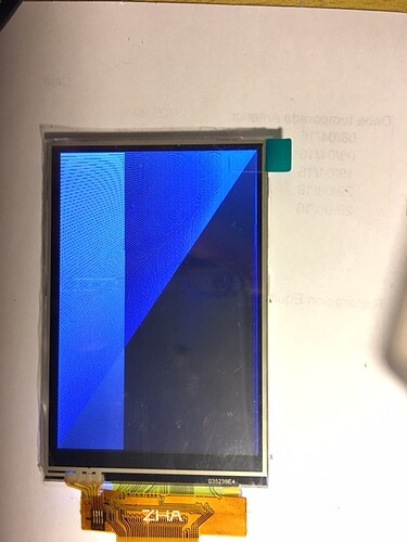
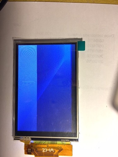
Hi, I'm excited, the screen work now, but don't work fine .

I modify the Begin in library again, with this code that I see in one web site, in this web speak from raspberry. But in the process of modify, I wrote wrong replace command, and I replaced all writedata register for writecommand :o

if (hwSPI) spi_begin();
  writecommand(0x11);		// Sleep OUT
	delay(50);
 
	writecommand(0xF2);		// ?????
	writecommand(0x1C);
	writecommand(0xA3);
	writecommand(0x32);
	writecommand(0x02);
	writecommand(0xb2);
	writecommand(0x12);
	writecommand(0xFF);
	writecommand(0x12);
	writecommand(0x00);

	writecommand(0xF1);		// ?????
	writecommand(0x36);
	writecommand(0xA4);

	writecommand(0xF8);		// ?????
	writecommand(0x21);
	writecommand(0x04);

	writecommand(0xF9);		// ?????
	writecommand(0x00);
	writecommand(0x08);

	writecommand(0xC0);		// Power Control 1
	writecommand(0x0d);
	writecommand(0x0d);

	writecommand(0xC1);		// Power Control 2
	writecommand(0x43);
	writecommand(0x00);

	writecommand(0xC2);		// Power Control 3
	writecommand(0x00);

	writecommand(0xC5);		// VCOM Control
	writecommand(0x00);
	writecommand(0x48);

	writecommand(0xB6);		// Display Function Control
	writecommand(0x00);
	writecommand(0x22);		// 0x42 = Rotate display 180 deg.
	writecommand(0x3B);

	writecommand(0xE0);		// PGAMCTRL (Positive Gamma Control)
	writecommand(0x0f);
	writecommand(0x24);
	writecommand(0x1c);
	writecommand(0x0a);
	writecommand(0x0f);
	writecommand(0x08);
	writecommand(0x43);
	writecommand(0x88);
	writecommand(0x32);
	writecommand(0x0f);
	writecommand(0x10);
	writecommand(0x06);
	writecommand(0x0f);
	writecommand(0x07);
	writecommand(0x00);

	writecommand(0xE1);		// NGAMCTRL (Negative Gamma Control)
	writecommand(0x0F);
	writecommand(0x38);
	writecommand(0x30);
	writecommand(0x09);
	writecommand(0x0f);
	writecommand(0x0f);
	writecommand(0x4e);
	writecommand(0x77);
	writecommand(0x3c);
	writecommand(0x07);
	writecommand(0x10);
	writecommand(0x05);
	writecommand(0x23);
	writecommand(0x1b);
	writecommand(0x00); 

	writecommand(0x20);		// Display Inversion OFF
	writecommand(0x00);//C8 	 

	writecommand(0x36);		// Memory Access Control
	writecommand(0x0A);

	writecommand(0x3A);		// Interface Pixel Format
	writecommand(0x55); 

	writecommand(0x2A);		// Column Addess Set
	writecommand(0x00);
	writecommand(0x00);
	writecommand(0x01);
	writecommand(0xDF);

	writecommand(0x002B);		// Page Address Set
	writecommand(0x00);
	writecommand(0x00);
	writecommand(0x01);
	writecommand(0x3f);	 
	delay(50);
	writecommand(0x0029);		// Display ON
	writecommand(0x002C);		// Memory Write
	if (hwSPI) spi_end();

For example, in pixel format I obtain 0x66 , not 0x55.

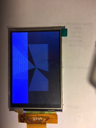
The screen show results in screen, I attach photos of this.

I write again the sequence with good writedata, when correspond and the result are same of always, pixel format 0x55 but screen in gray forever :frowning:

Can you help me to write a good sequence for initialize this screen please?

IMG_2236.JPG

IMG_2238.JPG

Are you using 9-bit SPI or 8-bit + DC SPI ?

The good news is that you have managed to read the registers.

If you are getting GREYs, the controller might be expecting 18-bit colour rather than 16-bit.
Try writing 0x66 to Reg(0x3A)

Personally, I would attempt to read 4 bytes from reg(0xBF) and 4 bytes from reg(0xD3). This would identify whether you have a Raydium RM68140 or an Ilitech ILI9486 or ILI9488.

What Arduino are you using? And with what wiring?

David.

Hi.
I use this configuration connections 3.5" SPI LCD touch screen ili9488 - #50 by indio99 - Displays - Arduino Forum.

In this secction of datasheet say

7.1.3. Serial Interface  
The selection of this interface is done by IM [2:0] bits. Please refer to the Table in the following.  
IM2 IM1 IM0 MPU-Interface Mode CSX D/CX SCL Function 
 1   0   1       3-line serial interface “L” -  Read/Write command, parameter or display data. 
 1   1   1       4-line serial interface “L” “L”/“H”  Read/Write command, parameter or display data. 
The ILI9486 supplies 3-lines/ 9-bit and 4-line/8-bit bi-directional serial interfaces for communication between the 
host and ILI9486. The 3-line serial mode consists of the chip enable input (CSX), the serial clock input (SCL) 
and serial data Input/Output (SDA). The 4-line serial mode consists of the Data/Command selection input 
(D/CX), chip enable input (CSX), the serial clock input (SCL) and serial data Input/Output (SDA) for data 
transmission. The data bus (D [17:0]) which are not used, must be leave these unused pins to open. Serial clock 
(SCL) is used for interface with MCU only, so it can be stopped when no communication is necessary.

I use 111 to IM0,1y2, I think that I set to 4-line SPI interface.

9-bit or 8-bit+DC SPI?, I don't understand this, How I know if I use one or other???

I try with your diagnostic code, but I always receive 0xFF or 0xFFFFFFFF, I not change any wire between codes, and I set correctly the pins definitions, and select 4-line SPI with this
char interface = NINEBITS; //ILI9341 SPI with regular MISO

I want probe your code, but I don't understand why don't work for me :S

Actually I use Arduino DUE and wiring hardware SPI port.

I change the begin sequence again, because I don't like much that this use write register that don't are in the datasheet, for example 0xF2, 0xF1, 0xF8, 0xF9
I comeback to last begin sequence, posted in last post, with 0x55 on 0x3A, same result, gray screen, then, I change 0x66 to 0x3A, and the screen show image same the attached photos on last post, small area of screen draw, and in grayscale text.

Thanks

From the datasheet:
IM=5 i.e. 1 0 1 DBI Type C Option 1 (3-line SPI) SDA/SDO
IM=7 i.e. 1 1 1 DBI Type C Option 3 (4-line SPI) SDA/SDO

You are using IM=7 i.e. 8-bit SPI + separate DC line.

I am surprised that you did not see anything from my diagnostic sketch.
Of course you have to #define the correct digital# pins.

And use

char interface = HAS_MISO;  //ILI9341 SPI

because you are using a regular 8-bit SPI with separate DC pin.

The ILI9341 reads multi-byte data differently to other chips. i.e. via reg(0xD9)

It is unfortunate that you are using the Due. If you had been using a 3.3V Uno, you could have just set USE_SERIAL and the MCUFRIEND_kbv library would have read the ID and configured itself for the correct controller.

As a general rule, Ilitek controllers will use 16-bit colours when you select reg(0x3A)=0x55.
The RM68140 seems to behave differently. It wants 0x66

David.

david_prentice:
And use

char interface = HAS_MISO;  //ILI9341 SPI

because you are using a regular 8-bit SPI with separate DC pin.

You are Great!!!

Now I received this from your diagnostic code:

data sheet specific calls
ILI9163C reg(0x04) = 0x548066
ILI9163C reg(0x09) = 0x00610000
ILI9163C reg(0x0A) = 0x08
ILI9163C reg(0x0B) = 0x00
ILI9163C reg(0x0C) = 0x66
ILI9163C reg(0x0D) = 0x00
ILI9163C reg(0x0E) = 0x00
ILI9163C reg(0x0F) = 0x00
ILI9163C reg(0x2E) = 0xA8A8A8
ILI9163C reg(0xA1) = 0x93309330
ILI9163C reg(0xBF) = 0x00000000
ILI9163C reg(0xD3) = 0xFFFFFFFF
ILI9163C reg(0xDA) = 0x54
ILI9163C reg(0xDB) = 0x80
ILI9163C reg(0xDC) = 0x66

ILI9163 why?, the seller are confused?

Thanks

The sketch reads reg(0x04). Most Ilitek controllers have xx 54 80 66 as default values.
Since the sketch was originally written for the ST7735/ILI9163 style of controller, that is what it reports.
As it happens, the Raydium controller returns the same default values.

Change these sequences for a new IS_9341 flag:

...
#define HAS_MISO  (1<<2)
#define IS_9341   (1<<3)
char *chip = "controller";
//char interface = 0;    //regular ST7735, ILI9163
//char interface = HAS_MISO | IS_9341;  //ILI9341 SPI
char interface = HAS_MISO;  //regular SPI
//char interface = NINEBITS | SDA_INPUT;  //ILI9481 SPI
...
    // works for an ILI9341 in 4-wire SPI mode
    if ((interface & IS_9341) && ((reg >= 0xB0 && reg < 0xF0)) ) {
        val = 0;
        d[0] = 0x10;
        while (bits > 0) {
            writeblock(0xD9, d, 1);       // CS sequence
            val <<= 8;
            val |= readwrite8(reg, 8, 0); // CS sequence
            bits -= 8;
            d[0]++;
        }
    }
    else val = readwrite8(reg, bits, dummy);
...

This should make it read reg(0xBF) and reg(0xD3) in a regular manner.

David.

Hi.

After modify your code, I obtain same results

data sheet specific calls
ILI9163C reg(0x04) = 0x548066
ILI9163C reg(0x09) = 0x00610000
ILI9163C reg(0x0A) = 0x08
ILI9163C reg(0x0B) = 0x00
ILI9163C reg(0x0C) = 0x66
ILI9163C reg(0x0D) = 0x00
ILI9163C reg(0x0E) = 0x00
ILI9163C reg(0x0F) = 0x00
ILI9163C reg(0x2E) = 0xA8A8A8
ILI9163C reg(0xA1) = 0x93309330
ILI9163C reg(0xBF) = 0x00000000
ILI9163C reg(0xD3) = 0xFFFFFFFF
ILI9163C reg(0xDA) = 0x54
ILI9163C reg(0xDB) = 0x80
ILI9163C reg(0xDC) = 0x66

0x0C value is 0x66, it's becuse this chip wait 18-bit pixels?

Thanks

Are you sure that you have edited correctly?
I would expect to see something for 0xD3

The diagnostic sketch reads the reset default values. All these controllers default to 18-bit.
The modified Adafruit sketch reads the current values i.e. after tft.begin() has initialised the chip.

A genuine Ilitek chip is capable of reading several multi-byte registers.

My diagnostic sketch is pretty easy to adapt. But first off, please check that you applied my edits first.

David.

Hi.

ok, I understand, this read default values of registers before changed anything.

yes, I edited your diagnostic code correctly, copy and paste overwriting with two portions of codes, posted from you, in last post.

Thanks.

Hi.

can I convert 16 depth color to 18 depth?, and then, send 18-bit pixel to the screen?. It's a crazy idea?

For convert 16 to 18 depth example

// RRRRR-GGGGGG-BBBBB, 16bit -->

//RRRRR0-GGGGGG-BBBBB0, 18bit with the formula below:
Color18 = ((Color16 & 0xF800) << 2) | ((Color16 & 0x07E0) << 1) | ((Color16 & 0x1F) << 1);

Then, in this case, I will need change the library for send 18 bit instead 16 ?

Thanks

Hi.

I modify the drawPixel() function on library, these:

void Adafruit_ILI9341::drawPixel(int16_t x, int16_t y, uint16_t [b]Color16[/b]) {

  if((x < 0) ||(x >= _width) || (y < 0) || (y >= _height)) return;

  if (hwSPI) spi_begin();
  setAddrWindow(x,y,x+1,y+1);

#if defined(USE_FAST_PINIO)
  *dcport |=  dcpinmask;
  *csport &= ~cspinmask;
#else
  digitalWrite(_dc, HIGH);
  digitalWrite(_cs, LOW);
#endif
  [b]uint32_t Color18 = ((Color16 & 0xF800) << 2) | ((Color16 & 0x07E0) << 1) | ((Color16 & 0x1F) << 1);
  //uint32_t Color18 = (Color16/32.0)*64;
  spiwrite(Color18 >> 16);[/b]
  spiwrite(Color18 >> 8);
  spiwrite(Color18);

#if defined(USE_FAST_PINIO)
  *csport |= cspinmask;
#else
  digitalWrite(_cs, HIGH);
#endif

  if (hwSPI) spi_end();
}

And now, The screen show correctly all blue pixels, the other colors not show correctly.

It's obvious that I not know to apply the code correctly, I don't know how apply convertion from 16 to 18 bit depth properly.

Other thing, I use an 32-bit core microcontroller, I don't use an avr8bit. Can I send directly 32 bit data over spi bus?, if yes, in these case, I will can send 18 bit data in one step?.

Can you help me to implement correctly the transfer 18 bit to screen?, And I think that is much better create a table of color on 18 bit depth instead convert from 16 to 18.

I attach some photos with these modification

Thanks

Hi.

I'm very happy.

I write this code and work fine for convert and send correctly to the screen from 565 to 666 RGB

uint32_t Color18 = ((Color16 & 0xF800) << 2) | ((Color16 & 0x07E0) << 1) | ((Color16 & 0x1F) << 1);
	spiwrite(Color18 >> 12);
	spiwrite((Color18 << 20) >> 26);
    spiwrite((Color18 << 26) >> 26);

Now, my screen work fine in 0x66 pixel format :slight_smile:

Thanks

Hi.

I edited adafruit library and adafruit_gfx to acept 32bit color instead 16bit, and i created a color table in 18 bit depth to use directly, instead convert on the fly 16 to 18 depth. I think that this optimize procesor time.

Work very well.

Only one thing, for use 18 depth color, send three bytes, 24 bits for pixel, this is 1/3 more slow than 16 depth because this send 24 bits instead 16.

I will try optimize to more fast write on screen, but I don't find the RM68140 Datasheet, have you this document? Can You send me this document? or where can I find this?

Thanks

Attila obtained the datasheet see this thread

If you PM me with your email, I can send you a copy.

There seem to be several differences between the RM68140 and a ILI9486.
Note that I have only got a write-only shield and hence I am only 99.5% confident that it is RM68140.

There are several members with readable displays i.e. Uno Mcufriend shields.
You can see what these "read" by looking through the linked thread and see the output from my (parallel) LCD_ID_readreg sketch.

Personally, I would concentrate on a 100% identification of the controller first.
Then I would investigate the reg(0x36) behaviour. e.g. try setRotation() for all 4 directions.

Likewise the reg(0x3A) behaviour. 8-bit, 16-bit, 18-bit coloured pixels.

David.

Hi David.

I test your diagnostic code, and the modified adafruit library for receive at least 32bit of registers reads, and this is the results.

With your code on DUE, STM32F103C and NODEMCU the results are same.

Read registers 8-bit SPI with MISO (+ DC)
data sheet specific calls
ILI9163C reg(0x04) = 0x548066
ILI9163C reg(0x09) = 0x00610000
ILI9163C reg(0x0A) = 0x08
ILI9163C reg(0x0B) = 0x00
ILI9163C reg(0x0C) = 0x66
ILI9163C reg(0x0D) = 0x00
ILI9163C reg(0x0E) = 0x00
ILI9163C reg(0x0F) = 0x00
ILI9163C reg(0x2E) = 0xA8A8A8
ILI9163C reg(0xA1) = 0x93309330
ILI9163C reg(0xBF) = 0x00000000
ILI9163C reg(0xD3) = 0xFFFFFFFF
ILI9163C reg(0xDA) = 0x54
ILI9163C reg(0xDB) = 0x80
ILI9163C reg(0xDC) = 0x66
ILI9163C reg(0x36) = 0x0000

And with same boards with modified adafruit library are same results, but different from your code

Display Power Mode: 0x9C
MADCTL Mode: 0x28
Pixel Format: 0x66
Image Format: 0x0
Self Diagnostic: 0x0
----------------------------------------------
0x04: 0x2A4033
0x05: 0x0
0x09: 0xCA318200
0x0A: 0x9C
0x0B: 0x28
0x0C: 0x66
0x0D: 0x0
0x0E: 0x0
0x0F: 0x0
0x45: 0x0
0x52: 0x0
0x54: 0x0
0x56: 0x0
0x5F: 0x0
0xAA: 0x0
0xAF: 0x0
0x2E: 0xA8A8
0xA1: 0xC9984998
0xBF: 0x0
0xD3: 0xFFFFFFFF
0xDA: 0x54
0xDB: 0x80
0xDC: 0x66
0xB0: 0x0
0x36: 0x0

This is your code, you send me some changes in last post, and this is the result after this modifications

// see if 4-line mode can read anything

#define TFT_MOSI 4//D7//75
#define TFT_MISO 5//D6//74
#define TFT_SCK  6//D5//76
#define TFT_SS   9//D1//9
#define TFT_DC  10//D2//10     //DC=7 for HX8347
#define TFT_RESET 8//D3//8   //Backlight on HX8347
#define NINEBITS  (1<<0)
#define SDA_INPUT (1<<1)
#define HAS_MISO  (1<<2)
#define IS_9341   (1<<3)
char *chip = "controller";
//char interface = 0;    //regular ST7735, ILI9163
//char interface = HAS_MISO | IS_9341;  //ILI9341 SPI
char interface = HAS_MISO;  //regular SPI
//char interface = NINEBITS | SDA_INPUT;  //ILI9481 SPI

uint32_t readwrite8(uint8_t cmd, uint8_t bits, uint8_t dummy)
{
    digitalWrite(TFT_SS, LOW);
    write9(cmd, 0);
    uint32_t ret = read8(bits, dummy);
    digitalWrite(TFT_SS, HIGH);
    return ret;
}

void write9(uint8_t val, uint8_t dc)
{
    pinMode(TFT_MOSI, OUTPUT);
    digitalWrite(TFT_DC, dc);
    if (interface & NINEBITS) {
        digitalWrite(TFT_MOSI, dc);
        digitalWrite(TFT_SCK, HIGH);
        digitalWrite(TFT_SCK, LOW);
    }
    for (int i = 0; i < 8; i++) {   //send command
        digitalWrite(TFT_MOSI, (val & 0x80) != 0);
        digitalWrite(TFT_SCK, HIGH);
        digitalWrite(TFT_SCK, LOW);
        val <<= 1;
    }
}

void writeblock(uint8_t cmd, uint8_t *block, int8_t N)
{
    uint8_t val = cmd;
    digitalWrite(TFT_SS, LOW);
    write9(cmd, 0);
    while (N-- > 0) write9(*block++, 1);
    digitalWrite(TFT_SS, HIGH);
}

uint32_t read8(uint8_t bits, uint8_t dummy)
{
    uint32_t ret = 0;
    uint8_t SDA = (interface & HAS_MISO) ? TFT_MISO : TFT_MOSI;
    pinMode(SDA, INPUT_PULLUP);
    digitalWrite(TFT_DC, HIGH);
    for (int i = 0; i < dummy; i++) {  //any dummy clocks
        digitalWrite(TFT_SCK, HIGH);
        digitalWrite(TFT_SCK, LOW);
    }
    for (int i = 0; i < bits; i++) {  // read results
        ret <<= 1;
        if (digitalRead(SDA)) ret |= 1;;
        digitalWrite(TFT_SCK, HIGH);
        digitalWrite(TFT_SCK, LOW);
    }
    return ret;
}

void showreg(uint8_t reg, uint8_t bits, uint8_t dummy)
{
    uint32_t val, mask = 0x10000000;
    for (uint8_t wid = 32; wid > bits; wid -= 4) mask >>= 4;
    writeblock(0x01, NULL, 0);   //software reset first
    delay(100);
    uint8_t d[4];
    if (interface & SDA_INPUT) {
        d[0] = 0x00;
        writeblock(0xB0, d, 1);  //UNLOCK
        d[0] = 0x80;
        writeblock(0xC6, d, 1);  //enable SDA as input
    }
// works for an ILI9341 in 4-wire SPI mode
    if ((interface & IS_9341) && ((reg >= 0xB0 && reg < 0xF0)) ) {
        val = 0;
        d[0] = 0x10;
        while (bits > 0) {
            writeblock(0xD9, d, 1);       // CS sequence
            val <<= 8;
            val |= readwrite8(reg, 8, 0); // CS sequence
            bits -= 8;
            d[0]++;
        }
    }
    else val = readwrite8(reg, bits, dummy);

    Serial.print(chip);
    Serial.print(" reg(0x");
    if (reg < 0x10) Serial.print("0");
    Serial.print(reg , HEX);
    Serial.print(") = 0x");
    while (val < mask) Serial.print("0"), mask >>= 4;
    if (val) Serial.println(val, HEX);
    else Serial.println();

}

void setup() {
    // put your setup code here, to run once:
    uint32_t ID = 0;
    Serial.begin(115200);
    while (!Serial) ;
    delay(3000);
    if (interface & HAS_MISO)
        Serial.println("Read registers 8-bit SPI with MISO (+ DC)");
    else if (interface & NINEBITS)
        Serial.println("Bi-directional Read registers 9-bit SPI");
    else
        Serial.println("Bi-directional Read registers SDA (+ DC)");
    digitalWrite(TFT_SS, HIGH);
    //    digitalWrite(TFT_SCK, HIGH);
    pinMode(TFT_SS, OUTPUT);
    pinMode(TFT_SCK, OUTPUT);
    pinMode(TFT_MOSI, OUTPUT);
    pinMode(TFT_MISO, INPUT);
    pinMode(TFT_DC, OUTPUT);
    pinMode(TFT_RESET, OUTPUT);
    digitalWrite(TFT_RESET, HIGH);
    digitalWrite(TFT_RESET, LOW);   //Hardware Reset
    delay(50);
    digitalWrite(TFT_RESET, HIGH);
    writeblock(0x01, NULL, 0);            //Software Reset
    delay(100);
    ID = readwrite8(0x04, 24, 1);
    if (ID == 0x7C89F0uL) chip = "ST7735S";
    if (ID == 0x548066uL) chip = "ILI9163C";
    ID &= 0xFF0000;
    if (ID == 0x5C0000) chip = "ST7735";
/*
    Serial.println("Scan all registers for any response");
    for (uint8_t reg = 0; reg < 0xFF; reg++) {
        if (readwrite8(reg, 32, 0) != 0xFFFFFFFF)
            showreg(reg, 32, 0);
    }
*/
    Serial.println("data sheet specific calls");
    showreg(0x04, 24, 1);  //RDDID
    showreg(0x09, 32, 1);  //RDDSTATUS
    showreg(0x0A, 8, 0);
    showreg(0x0B, 8, 0);   //RDDMADCTL
    showreg(0x0C, 8, 0);   //RDDCOLMOD
    showreg(0x0D, 8, 0);
    showreg(0x0E, 8, 0);
    showreg(0x0F, 8, 0);
    showreg(0x2E, 24, 8);  //readGRAM
    showreg(0xA1, 32, 1);  //ILI9481 DDB_Start
    showreg(0xBF, 32, 1);  //ILI9481 ID
    showreg(0xD3, 32, 1);  //RDID4 according to data sheet
    showreg(0xDA, 8, 0);   //RDID1
    showreg(0xDB, 8, 0);   //RDID2
    showreg(0xDC, 8, 0);   //RDID3
    showreg(0x36, 16, 0);   //RDID3
}

void loop() {
    // put your main code here, to run repeatedly:

}

#if defined(USE_SPI)
// use SPI mode #0
uint8_t spi(uint8_t c)
{
    SPDR = c;
    while ((SPSR & 0x80) == 0) ;
    return SPDR;
}

uint32_t readwrite8(uint8_t cmd, uint8_t bits, uint8_t dummy)
{
    uint32_t ret = 0;
    uint8_t val = cmd;
    int cnt = 8;
    digitalWrite(TFT_SS, LOW);
    SPSR = (0 << SPI2X);
    SPCR = (1 << SPE) | (1 << MSTR) | (1 << SPR0); //1MHz
    digitalWrite(TFT_DC, LOW);
    pinMode(TFT_MOSI, OUTPUT);
    spi(cmd);
    if (bits) {
        digitalWrite(TFT_DC, HIGH);
        pinMode(TFT_MOSI, INPUT);
        while (bits) {
            ret <<= 8;
            ret |= spi(0x00);
            bits -= 8;
        }
        ret >>= dummy;
    }
    digitalWrite(TFT_SS, HIGH);
    return ret;
}
#endif

And this is the modifications that I need to do in the adafruit library, for read more than 8 bit form spi

void CodeTronic_ILI9486::dummyclock(void) {
 if (hwSPI) spi_begin();
 digitalWrite(_sclk, LOW);
 digitalWrite(_sclk, HIGH);
if (hwSPI) spi_end();
 } 

 uint16_t CodeTronic_ILI9486::readcommand16(uint8_t c) {
 if (hwSPI) spi_begin();
 digitalWrite(_dc, LOW);
 digitalWrite(_sclk, LOW);
 digitalWrite(_cs, LOW);
 
 spiwrite(c);
 digitalWrite(_dc, HIGH);
 uint16_t r = spiread();
 r <<= 8;
 dummyclock();
 r |= spiread();
 digitalWrite(_cs, HIGH);
 if (hwSPI) spi_end();
 return r;
 }
 
  uint32_t CodeTronic_ILI9486::readcommand24(uint8_t c) {
 if (hwSPI) spi_begin();
 digitalWrite(_dc, LOW);
 digitalWrite(_sclk, LOW);
 digitalWrite(_cs, LOW);
 
 spiwrite(c);
 digitalWrite(_dc, HIGH);
 uint32_t r = spiread();
 r <<= 8;
 dummyclock();
 r |= spiread();
 r <<= 8;
 dummyclock();
 r |= spiread();
 digitalWrite(_cs, HIGH);
 if (hwSPI) spi_end();
 return r;
 }
 
 uint32_t CodeTronic_ILI9486::readcommand32(uint8_t c) {
 if (hwSPI) spi_begin();
 digitalWrite(_dc, LOW);
 digitalWrite(_sclk, LOW);
 digitalWrite(_cs, LOW);
 
 spiwrite(c);
 digitalWrite(_dc, HIGH);
 
 uint32_t r = spiread();
 r <<= 8;
 dummyclock();
 r |= spiread();
 r <<= 8;
 dummyclock();
 r |= spiread();
 r <<= 8;
 dummyclock();
 r |= spiread();
 digitalWrite(_cs, HIGH);
 if (hwSPI) spi_end();
 return r;
 }

After this results, I don't know what are my tft chip controller, with 0x55 pixel format don't work with any way

In the RM68140 datasheet, say DOPCTR (Display Option Control), reg 0x76. I think that in this register you can apply the pixel format, but dont work for me, I try with some changes in this register without positive results.

Regards

Your Adafruit mods are wrong. Think about it. reg(0x04) should contain 54 80 66 to match regs 0xDA, DB, DC.
You do not need a dummy clock between each byte.

I am still surprised that you are not getting something from reg(0xBF) and reg(0xD3).

There are several other multi-byte registers. You could try reading them.

If you are still struggling, I could post you a "library". But since I do not have your particular SPI chip, I would need to read / see the results via message / video.

David.

Hi David.

I try again my adafruit modification library exactly without dummyclock() between read bytes and the result are exactly same to last result with this library with dummyclock()

Not there variation.

And this is the new serial output with add new registers

ILI9163C reg(0x04) = 0x548066
ILI9163C reg(0x05) = 0x00
ILI9163C reg(0x09) = 0x00610000
ILI9163C reg(0x0A) = 0x08
ILI9163C reg(0x0B) = 0x00
ILI9163C reg(0x0C) = 0x66
ILI9163C reg(0x0D) = 0x00
ILI9163C reg(0x0E) = 0x00
ILI9163C reg(0x0F) = 0x00
ILI9163C reg(0x2E) = 0xA8A8A8
ILI9163C reg(0xA1) = 0x93309330
ILI9163C reg(0xBF) = 0x00000000
ILI9163C reg(0xD3) = 0xFFFFFFFF
ILI9163C reg(0xDA) = 0x54
ILI9163C reg(0xDB) = 0x80
ILI9163C reg(0xDC) = 0x66
ILI9163C reg(0x36) = 0x0000
ILI9163C reg(0x45) = 0x00
ILI9163C reg(0x52) = 0x00
ILI9163C reg(0x54) = 0x00
ILI9163C reg(0x56) = 0x00
ILI9163C reg(0x5F) = 0x00
ILI9163C reg(0xAA) = 0x00
ILI9163C reg(0xAF) = 0x00

I understand, ID1, ID2 and ID3 are same to 0x04 in your code, and not same result in my code.

I found this, it's can have relationated with these

# Read display identification information (04h) 
        # The 2nd parameter (ID1 [7:0]): LCD modules manufacturer ID. 
        # The 3rd parameter (ID2 [7:0]): LCD module/driver version ID. 
        # The 4th parameter (ID3 [7:0]): LCD module/driver ID. 
        d.read_reg(0x04, 3)
        # tinylcd35: 0x2A, 0x40, 0x33
        #   ID1 = 0x2A -> This does not match register 0xDA = 0x54  but (0x2A >> 1) = 0x54
        #   ID2 = 0x40 -> This does not match register 0xDB = 0x80  but (0x80 >> 1) = 0x40
        #   ID3 = 0x33 -> This does not match register 0xDC = 0x66  but (0x66 >> 1) = 0x33

If you are still struggling, I could post you a "library". But since I do not have your particular SPI chip, I would need to read / see the results via message / video.

I'm very interested to do work this screen, well and fast in SPI interface, it's marvelous if you do a library for these, but I understand that this is complicated, much complicated if you don't have these screen fisicaly.

If you want, I can send by mail post this screen, with my homemade pcb adapter to you.

I'm interested to learn, learn and learn, and with your help, I'm sure that this screen i'll do work very fine :slight_smile:

Thanks