Hello I want measure voltage between 3 phases, please not i dont have neutral, with neutral we can easily measure using 3 step down transformers, but here i just have 3 phases.
so want to measure voltage between phase to phase which 440v.
I need this circuit to detect phase failure.
Hello mrnams
Take a view here to gain the knowledge:
To measure the voltage you just need three appropriately rated voltage transformers across phase to phase , and measure the now isolated low voltage ( lightly loaded transformer ) .
You obviously need someone qualified to spec and install them .
Alternatively how about small neons across each phase and detect the light . Use a plastic tube to give isolation - again seek advice to get it installed.
Or buy a phase failure relay
Oh and why do you need this ?
In that case, the three wires share the voltage of adjacent phases. You absolutely must have three transformers to separate the phase voltage so you can measure each one separately.
I mean i have to detect it with arduino, with neon we can detect is with eye but need input to arduino and based on those value i shall decide to turn on 3phase motor or not
These will measure current flowing through it, i need to check voltage in each phase, like phase to phase 440volt, R-Y=440v,Y-B=440v and B-R=440v
You are not paying attention to the FACT that an Arduino can ONLY measure voltages between some source and IT'S ground connection. It cannot measure between two high voltage wires. That is why transformers are required to do your measurements.
Just thinking out loud.
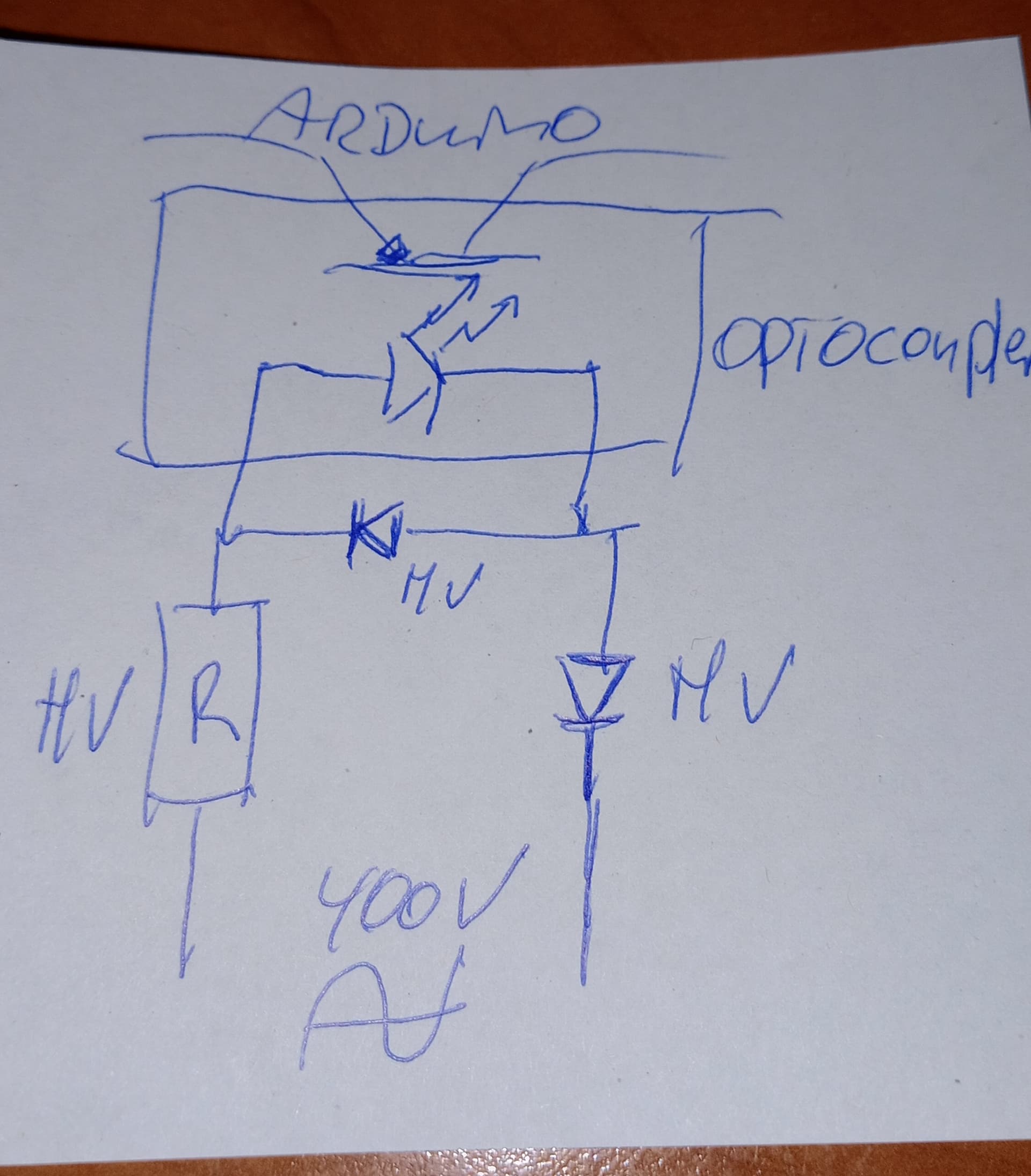
If you can drive the led side of 3 optocouplers directly from the phases (triangle setup), by adding a decent HV series resistor and maybe an extra high voltage diode in series and a HV diode as flyback across the optocoupler led. (probably the optocoupler led cannot withstand the reverse voltage itself) you should observe pulses in the optocoupler with the frequency of the AC.
Then monitor those 3 frequencies with your Arduino and when one phase fails I would expect 2 out of the 3 frequencies will disappear. Only the optocupler between the two working phases would continue to switch on/of/on/of...etc.
The optocouplers would also take care of the galvanic isolation.
my 2 cents.
This makes sense,i shall study in this way, thanks a lot.
Other option i am thinking it's to use three 440v to 12v step down transformer and then measure voltage
Isn't that what @hammy suggested?
please not the OP does not have "Y" 3-phase power, which youall are basing your circuits on. Each of the three wires will also carry voltage from the adjacent phases, but they will not be in phase, but will overlap.
Might help :
Read me
Thank you all for valuable response.
Based on your input I shall study littel bit more and share my solution for your approval
I think I did not base my schematic on a "Y" setup but a triangle setup.
Can you explain if that is a problem for the circuit I suggested?
When I look at a picture of the 3-phase voltages

They are all crossing each other at 120 degree angles and therefore resulting in any phase being lower 50% of the time than any other phase (and higher the other 50%).
That is all well and good, but your circuit will always have the optio-isolator turned on, as shown in your graph. Remember, the opto-isolator is producing a digital, off-on signal for the Arduino.
Now I am confused about what you mention about the opto isolator.
Imagine the opto isolator between the blue and the red phase in above picture.
At timepoint 20 the blue voltage is higher than the red voltage and depending on the orientation of the IR led inside the optoisolator it will be on or off. Let's assume it is now on.
Now at timepoint 50 the red voltage is higher than the blue voltage, so the IR led inside the optoisolator will be off.
I'll let you test it.
I interpret your answer, that you are unable to substantiate your statement with logic and leave it to me testing. That's fine.
But if you just measure across one phase you won’t see that overlapping that you show , which is meaningless .
My idea with neons was that you could sense the light with an ldr and use that to tell the Arduino that the phase is ok .
For safety if you must connect directly use transformers , don’t bring 440v onto your circuit boards !!!