OK. I see. It appears that in your original program you have used the physical package pin numbers instead of the "Arduino" pin numbers. As I said, I assumed these were correct. Anyway, the revised code appears below:
// 6 Digit Nixie - Revised pins
// ATMEGA328P
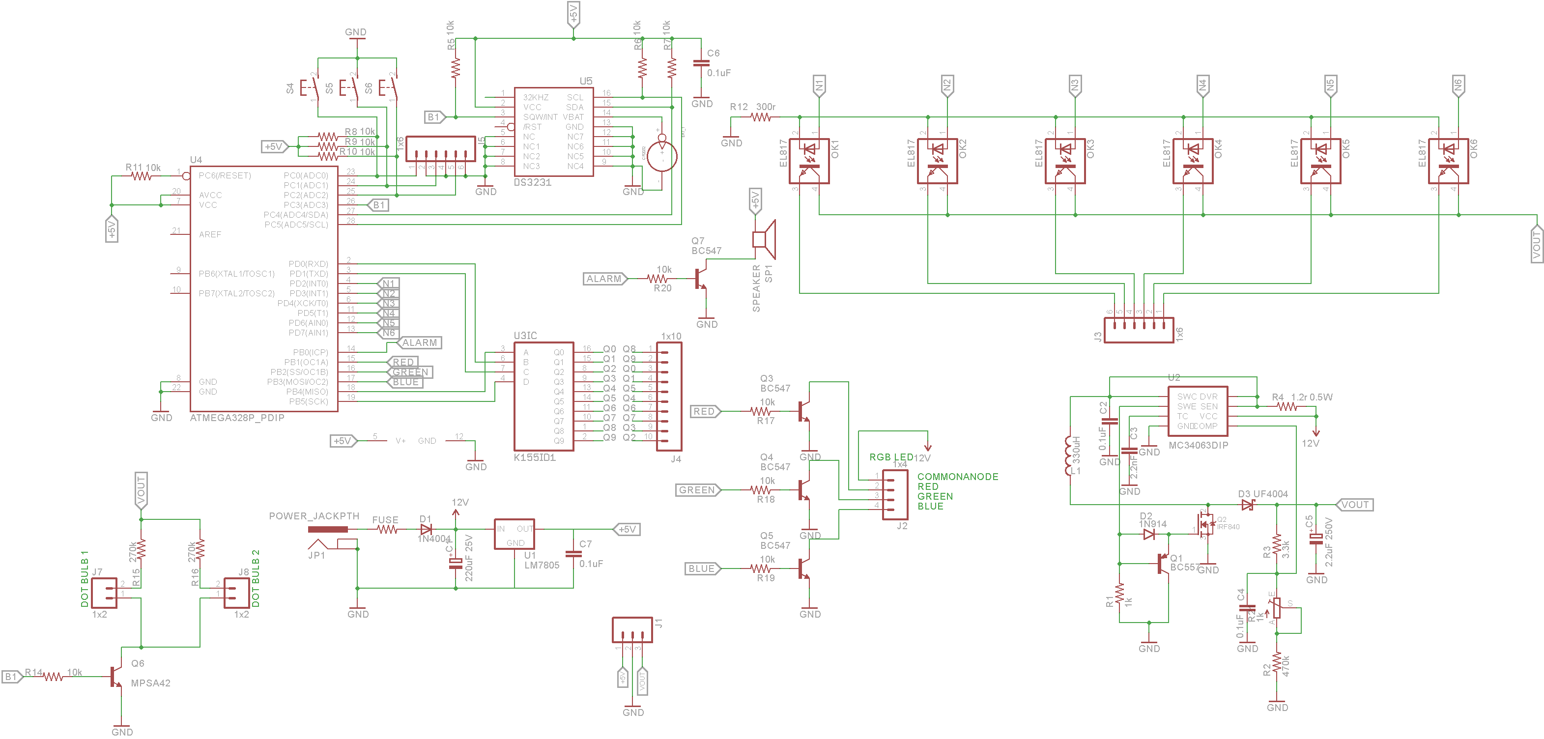
#define A 12 // pin 3 on the K1551D1 Chip
#define B 0 // pin 6 on the K1551D1 Chip
#define C 1 // pin 7 on the K1551D1 Chip
#define D 13 // pin 4 on the K1551D1 Chip
// #define N1 2 // Nixie Tube 1
// #define N2 3 // Nixie Tube 2
// #define N3 4 // Nixie Tube 3
// #define N4 5 // Nixie Tube 4
// #define N5 6 // Nixie Tube 5
// #define N6 7 // Nixie Tube 6
// #define UP 23 // Menu UP physical pin !
// #define DN 24 // Menu Down physical pin !
// #define MU 25 // Enter Menu physical pin !
// #define AL 14 // Alarm out physical pin !
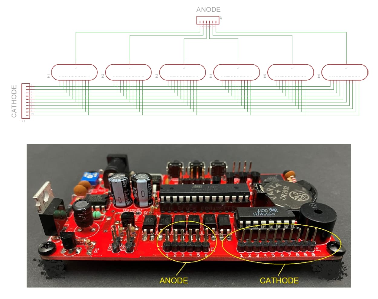
// anode pins - tubes numbered 0 to 5
const uint8_t anodes[6] = { 2, 3, 4, 5, 6, 7 };
// for later optimisation
uint8_t digits[10][4]{
{ 0, 0, 0, 0 }, // 0
{ 0, 0, 0, 1 }, // 1
{ 0, 0, 1, 0 }, // 2
{ 0, 0, 1, 1 }, // 3
{ 0, 1, 0, 0 }, // 4
{ 0, 1, 0, 1 }, // 5
{ 0, 1, 1, 0 }, // 6
{ 0, 1, 1, 1 }, // 7
{ 1, 0, 0, 0 }, // 8
{ 1, 0, 0, 1 } // 9
};
// change this if required
uint8_t display[6] = { 0, 9, 1, 4, 5, 2 }; // this should appear on the display
void setup() {
Serial.begin(115200);
pinMode(A, OUTPUT);
pinMode(B, OUTPUT);
pinMode(C, OUTPUT);
pinMode(D, OUTPUT);
for (uint8_t i = 0; i < 6; i++) {
pinMode(anodes[i], OUTPUT);
}
}
void loop() {
static uint32_t laststrobeAtMs = 0;
static uint8_t tube = 0;
if (millis() - laststrobeAtMs > 4 ) { // more than 5ms gives flicker
laststrobeAtMs = millis();
for (uint8_t i = 0; i < 6; i++) digitalWrite(anodes[i], LOW); // all tubes off
// for later optimisation
digitalWrite(A, digits[display[tube]][3]);
digitalWrite(B, digits[display[tube]][2]);
digitalWrite(C, digits[display[tube]][1]);
digitalWrite(D, digits[display[tube]][0]);
/*
Serial.print ("tube ") ;
Serial.println( tube );
Serial.print (digits[display[tube]][3]) ;
Serial.print (digits[display[tube]][2]) ;
Serial.print (digits[display[tube]][1]) ;
Serial.print (digits[display[tube]][0]) ;
Serial.println() ;
*/
digitalWrite(anodes[tube], HIGH); // switch current tube anode on
if ( ++tube >= 6) tube = 0; // cycle to next tube
// any other code goes here - don't block for too long
}
}
I'm not sure what you mean when you say this
On the target Nixie board there is not external oscillator (Crystal). If you have told it there was one, you may have bricked the chip, that is until you can supply an external oscillator and reprogram it. But the fuse settings (post#21) look correct apart from the CKDIV8 which looks odd.
On what device did you compile the code ? Can Microchip Studio compile Arduino code ?