I'm tring to setup a lipo Battery monitor using an Arduino Nano and an I2C 128x64 Display OLED.
I have surf and found many example to do it, and I have implement this code :
The code work but I have a problem that the read value is not stable, I mean the values have a window from 4.14V to 4.25V but for all the cells the voltage measured with a multi meter is 4.18V-4.19V.
I 'm became crazy with un-useful small code refinements or voltage divider value correction >:( , but nothing change the results. The values are still be from 4.14V to 4.25V .
Any suggestions?
Delta_G:
Sometimes when you're changing pins between reads you get slightly unstable readings. Some folks will read the pin twice and only keep the second reading if they just changed pins. That might be worth trying.
Not worth trying as the impedance of the divider is less than 10k. The issue is for high impedance sources the
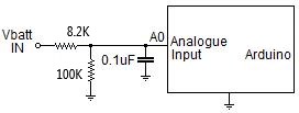
sample capacitor in the ADC doesn't have enough chance to charge up - for source impedances of 10k or less this is never an issue. The impedance of a 8k2/100k divider is 7k6 as the resistors are effectively in parallel for this use (battery has a low impedance).
My question is what is Vcc? If its 5.0V, then a 8k2/100k divider won't work. And for a 3S LiPo pack that's certainly not going to work.
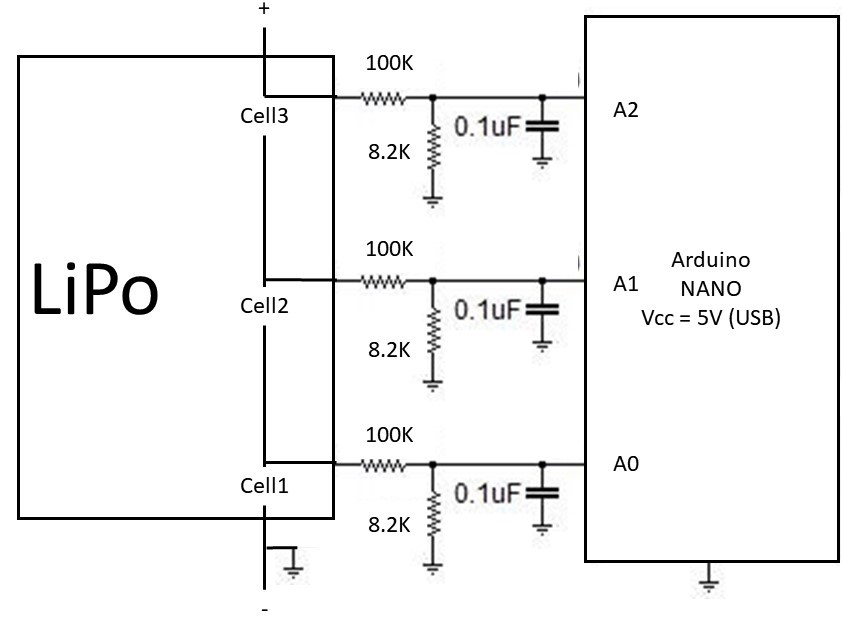
A 100k/8k2 divider I could believe, especially given the INTERNAL ADC reference setting. Perhaps the circuit diagram should be corrected, and extended to include all the cells...
Post a picture showing the grounding scheme.
To measure that battery correctly, Arduino ground and battery negative must be short and not carry other significant currents.
Leo..
Couple of things ...
Write your own code !
I would use the internal voltage reference of the Arduino, without that you are comparing the battery voltage to the arduino supply , which might be wandering about.
I would do all the maths as integers , there is no extra accuracy gained by using floats -Work all your values in mV ( look at map) and add the decimal point only when you display it .
You can buy quite cheap Lipo meters with balancing , discharge to storage voltage etc
Don’t forget if 0-5v gives 0-1023 ; then you can’t get more accurate than 5mV. +/- 5mV accounts for some of the error you are seeing, eg: 4.20v , 4.19v. If you are “ “mapping”. The analog reading to a voltage , then you will get some additional rounding errors .
your link is very interesting, and I will use it for my project. I understand read errors but what I don't understand, why I have this variability on the reads with a difference of 5 points:
For the other contributors, I have try to make multiple reads and do the average of it, trash the first 10 reads, I have try to use the INTERNAL Aref and the EXTERNAL using the 3.3V pin, but at te end nothing solve the variability of the read values.
Not sure why you are seeing that. The Arduino with a 5 volt reference and 2^10 A/D will give a 4.88 mV (figure 5 mV) resolution so that is as good as it gets and a little noise is normal Using an Arduino Uno to measure a DC voltage I normally get pretty decent stability. Glad you found the link interesting.