Hi everyone, I've recently received arduino uno rev3 and some starter kit. I learned to be able to do very simple project like a single LED blinking and programming a pattern of lighting for a row of LEDs. Now, I am trying to do 3x3. As I tried to google it, I can only find one tutorial that uses a specific breadboard that I use (a really small one!). It has the source code and schematic, and even has the video for demonstration. The problem is, I don't really understand how the schematic translates to setting up the breadboard. And the video is REALLY hard to see for wiring.
I don't know if I do bite more than I can chew. Should I start with reading guides on understanding schematics. I am able to understand some of those simple schematics but not like that one by Andrew Tuline in the link I just provided.
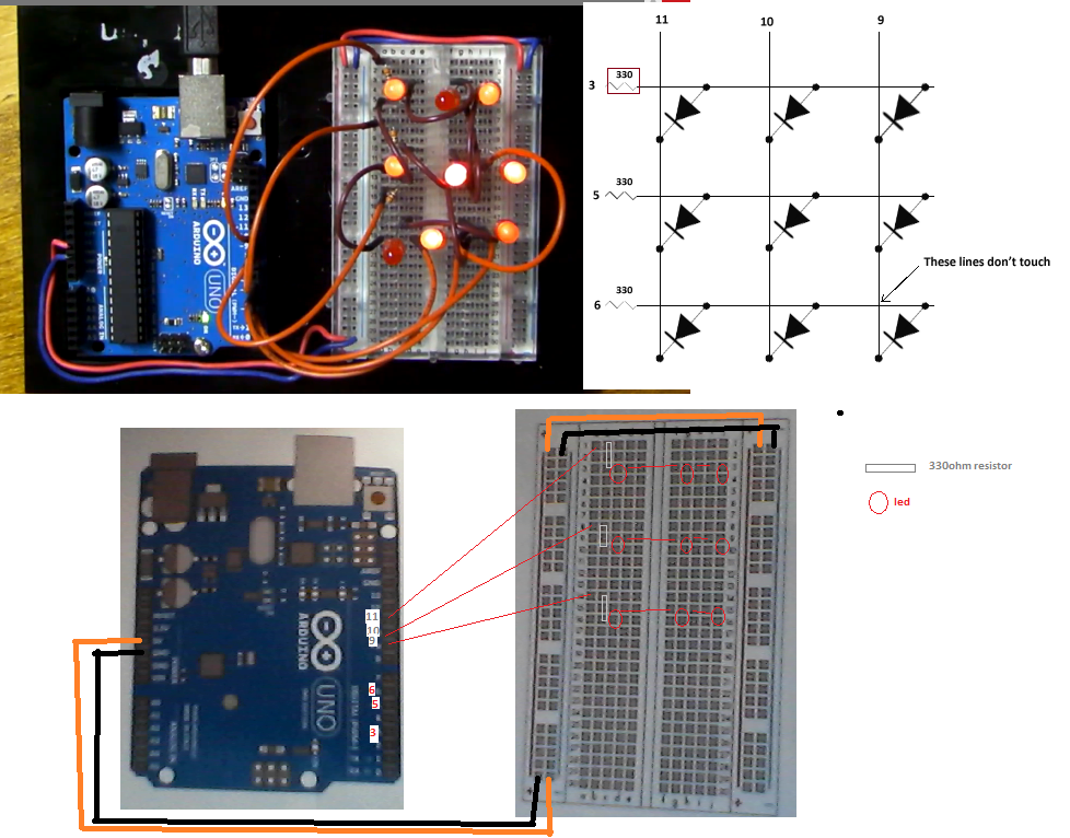
The Anode/Positive side of each LED is connected to a column pin. The Cathode/Negative side of each LED is connected through a 330 Ohm resistor to a row pin. Since the resistors are on the rows, only one column can be lit at a time. You light a column by setting its pin to LOW and you select which LED in that column are lit by setting those row pins to HIGH. Current flows from the row pin, through the resistor, through the LED, to the column pin.
The Arduino can only deal with 40 mA MAX in out out of any pin. If you want to be able to turn on all three LEDs in a column you have to limit the current to about 10 mA per LED to keep the total column current below the maximum. There are various web-based calculators out there that will calculate what resistor to use given the total voltage (5V) the voltage drop across the LED (depends on the LED) and the desired current.
This one says that if the voltage drop of your LED is 3V then you can go down to a 220 Ohm resistor and still get 10 mA current flow. The 330 Ohm resistors should be fine.
Thanks, that helps me understand how the Arduino works. I am still a bit confused about setting up the board... here is the drawing I made, and I really can't see how 3,5,6 pins are connected.