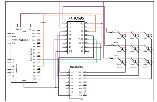
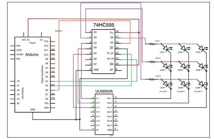
Hello, I am reading book „C Programming for Arduino” and I am not sure am I understand something wrong, or is there a mistake in the book.
So here is the code:
int CLOCK_595 = 4; // first 595 clock pin connecting to pin 4
int LATCH_595 = 3; // first 595 latch pin connecting to pin 3
int DATA_595 = 2; // first 595 serial data pin connecting to pin 2
int counter = 0;
boolean LED_states[9] ;

void setup() {
pinMode(LATCH_595, OUTPUT);
pinMode(CLOCK_595, OUTPUT);
 pinMode(DATA_595, OUTPUT);
 // use a seed coming from the electronic noise of the ADC
 randomSeed(analogRead(0));
}

void loop() {
 // generate random state for each 9 LEDs
 for (int i = 0 ; i < 9 ; i++)
 {
 LED_states[i] = random(2) ;
 }
 // initialize data at each loop()
 byte data = 0;
 byte dataRow = 0;
 byte dataColumn = 0;
 int currentLed = 0;
 // cycling columns
 for (int c = 0 ; c < 3 ; c++)
 {
 // write the 1 at the correct bit place (= current column)
 dataColumn = 1 << (4 - c);
 // cycling rows
 for (int r = 0 ; r < 3 ; r++)
 {
 // IF that LED has to be up, according to LED_states array
 // write the 1 at the correct bit place (= current row)
 if (LED_states[currentLed]) dataRow = 1 << (4 - c);
 // sum the two half-bytes results in the data to be sent
 data = dataRow | dataColumn;
 // Put latch pin to LOW (ground) while transmitting data to 595
 digitalWrite(LATCH_595, LOW);
 // Shifting Out bits
 shiftOut(DATA_595, CLOCK_595, MSBFIRST, data);
// Put latch pin to HIGH (5V) & all data are pushed to outputs
 digitalWrite(LATCH_595, HIGH);
 dataRow = 0; // resetting row bits for next turn
 currentLed++;// incrementing to next LED to process
 }
 dataColumn = 0;// resetting column bits for next turn
 }
 // each 5000 loop() execution, grab a new seed for the random function
 if (counter < 5000) counter++;
 else
 {
 randomSeed(analogRead(0)); // read a new value from analog pin 0
 counter = 0; // reset the counter
 }
 // pause a bit to provide a cuter fx
 delay(150);
}
I do not have shift registers so I am unable to test out this sketch by my own.
Confusion starts in line ” if (LED_states[currentLed]) dataRow = 1 << (4 - c);”.
Isn't there suppose to be (8-c) instead of (4-c) , due to sum of two half bytes in continue?
Thanks in advance ![]()

