Hello everyone,
I am having trouble making arduino 4-20mA interface. I am using 74HC4051 mux shield to switch 5 different pressure sensors to ADS1115 A0 input (ok maybe if i thought more before ordering I would have ordered 2 ADS1115 shields and have 8 inputs ready).
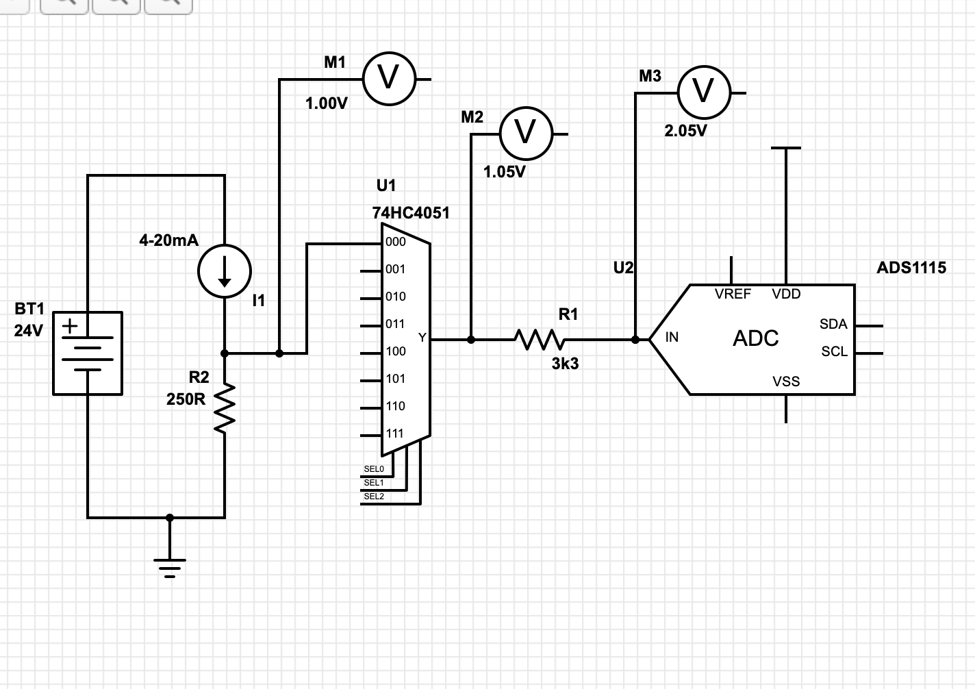
Basics: I have 5 4-20mA sensors connected in series with 250R resistor to have 1-5V output for ADC (I am using 24V DC-DC converter to power from 12V battery).
For 5V supply I am using arduino 5V bus, supplies grounds connected.
On the ADC input I put a 3k3 resistor to protect it. Problem is I have a large voltage rise on that resistor (1V).
I thought it would be voltage drop, but something is obviously off. The schematic attached should illustrate the problem. Also, the mux increases the voltage from 1V to 1.050V. It doesnt seem like much, but I am trying to build an interface that shouldn't have more than 0.1% total error so it matters. But that should be linear so I can just subtract it from ADC value.
Have any ideas what might I be doing wrong? Thanks!
Your circuit looks good. Be sure all the grounds are connected. From your schematic it appears you have a bad ADC because it is sourcing voltage into your circuit, it should not do that. Again check the grounds, they are extremely critical at these low voltages. Long wires can also cause problems and be sure you have adequate decoupling on the power supplies. You may also be connecting earth to the circuit via the USB to your computer.
Thank you very much for your fast reply!
You got it right, A0 input was fried, putting out 4.97V all the time. Probably mux inside the ADS1115 broke. Changed to A1 and it works like a charm, I'm glad the actual ADC input is ok. It did take some creative soldering though ![]()

PS Chinese also sold me ADS1015 for ADS1115 ![]()
250 ohm is the standard (wrong) value for a 5volt Arduino input (should be 51 ohm, with 1.1volt Aref),
but errors are repeated all over the internet.
You should use 100 ohm sense resistors for an ADS1115, and a PGA gain of two.
A (1N4004) diode across the 100 ohm resistor (anode to ground) could protect from reverse polarity.
The 4051 output should connect directly to the MCU, and the protection resistor should move to the 4051 input.
The 4051 input could have a 100n cap to ground, to short any RF noise.
Leo..
Yes, it would fill the ADC range better but that kind of precision is not critical for my application and I guess lower voltage signals are more susceptible to RF interference and gremlins so I don't really like things to be below 5V (call me a dinosaur but in my head its like that). I agree about the protection diode and caps, I should have thought of that. Also I found out that my 4-20mA sensors put out more than 20mA when overloaded. I will probably make another board with 2xADS1115 and make it the way you said (including 100 ohm sense resistors).
Also you are right about the input protection resistor, it should be in front of the 4051.