I needed an MOSFET board to drive high current relays. I found this board,
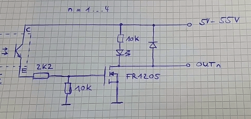
The specifications look pretty good, input voltage, 3 to 24V, power output voltage 3 to 55V. So I purchased it. At the time I did not have the above link. After finding the above link, I scrolled down and found a partial schematic on the unit, and i became very concerned, knowing that most N channel MOSFET's have a 20V gate to (-) limit. Now that I have it, I decided to check it out for myself.
I decided to do a basic profile on it.
Power input for the MOSFET was set at 27.5 V. This is half of the rated voltage.
Optocoupling input. Gate.
1.2V 2.28V this is when the MOSFET first triggered.
2.0V 15.60V
2.5V 25.20V this is well above the gate voltage limit.
3.0V 25.92V
4.0V 25.955V
5.0V 25.97V
10.0V 25.999V
15.0V 26.012V
20.0 V 26.019V
24.0V 26.020V that is a 1.3V drop.
at MOSFET power = 30V.
Optocoupling input. Gate.
24.0V 28.169V
And at MOSFET power = 50V.
Optocoupling input. Gate.
5.0V 45.589V
Remember this is a MOSFET. It only needs a static charge on the gate to turn it on. There is no actual current flow through the gate.
In my opinion, In order to make sure you do not exceed the gate threshold limit of the MOSFET, this board should not be used with a voltage higher than 20V power output.
This board needs to be redesigned. A Zener need to be added to the gate. Along with the better voltage divider.
Fortunately my project is limited to 12V. But if your project uses more than 20V, you may want to look for a different board.
