Until today I always did it with small black brackets with two servos from aliexpress.
Recently I was very impressed on that 28BYJ-48 stepper motor has 4096(!) half steps per revolution (and did build high precision (3µm accuracy) linear actuator from it): https://forum.arduino.cc/index.php?topic=645745.0
Today I received a box with 5 such stepper motors and 5 ULN2003 drivers.
Until today I had only one such stepper motor, and was not able to do what I did now.
4 drops of superglue are enough to create a high precision PT system!
Servos have range 0..180° with 180 steps (1 step/°).
28BYJ-48 has unlimited range and 4096 steps per 360° (11.3 steps/°).
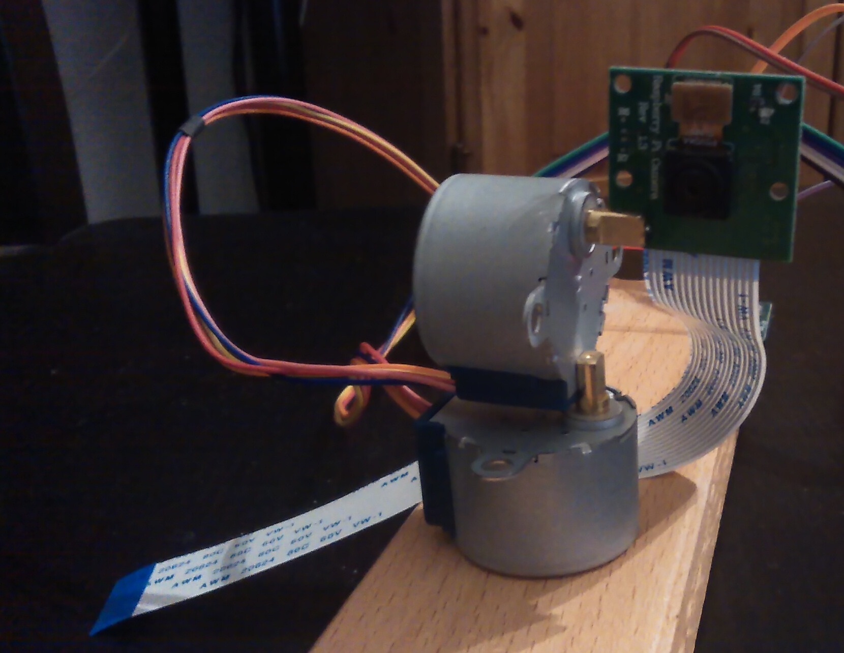
1st drop of superglue between ground plate and bottom steper motor.
2nd drop to fixate 4 cables leaving upper stepper horizontally.
3rd drop to fixate upper 28BYJ-48 directly on motor shaft of bottom stepper motor.
4th drop to fixate Raspberry v1 camera on upper stepper motor shaft.
That's all -- I don't know why I every used servos for PT camera system.
I did it, moved the 70mm lens from servo PT camera system to stepper PT system.
Upper stepper+lens weight is 36.4g+19.1g=55.5g -- lower stepper and superglue have no problems to deal with this.
Used this sample script to make joystick connected to A0 and A1 move the camera.
Horizontal range restricted to -90*..90°, vertical from 0°..90° (for tracking airplane through roof window):
Not earth-shatteringly robust of course, but works pretty well. Does the Pi camera board get damaged if you were to remove it from the motor for another use? I'd suspect it might.
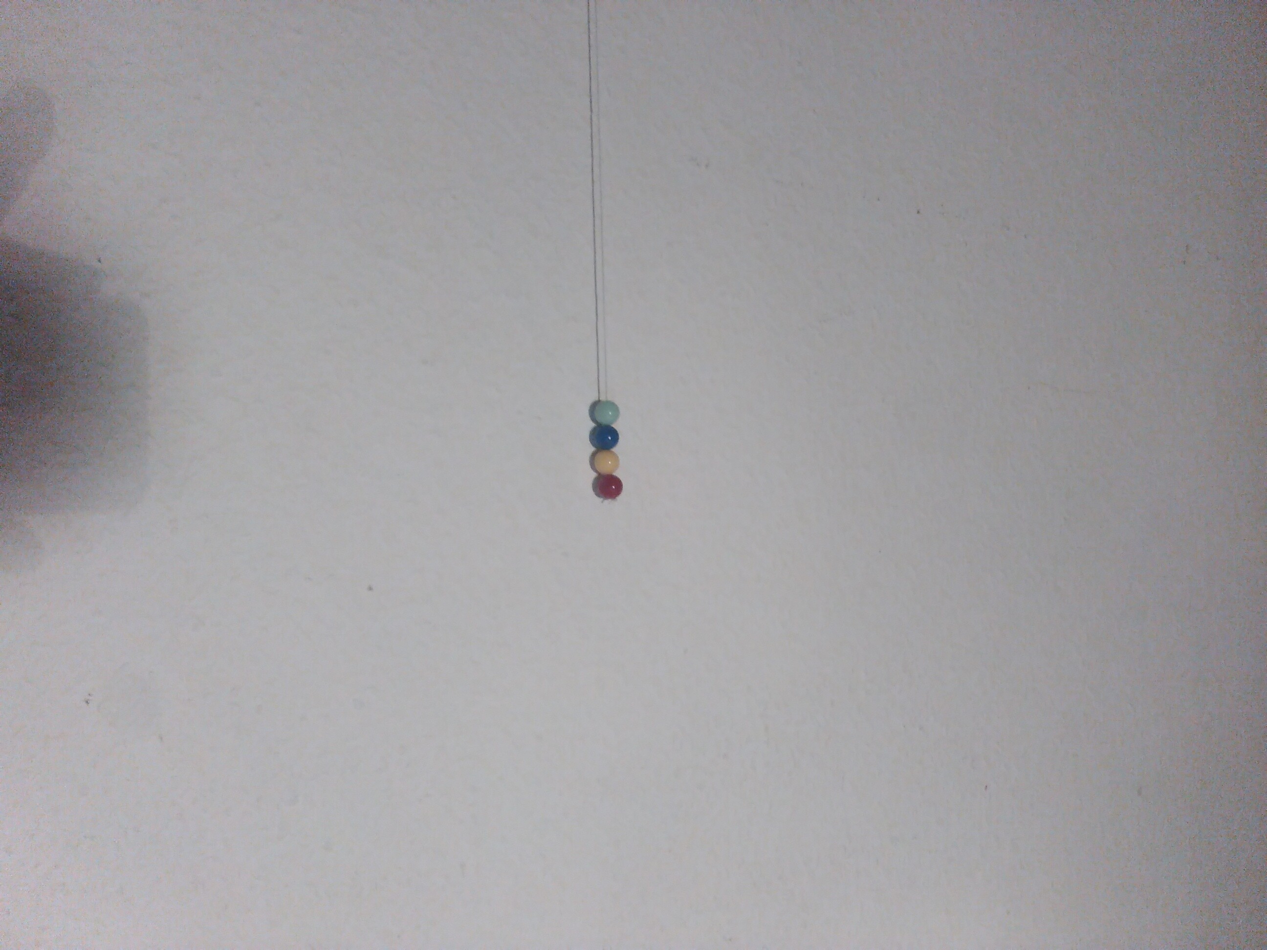
I will develop the airplane center algorithm inhouse, that is main reason for changing back 70mm lens camera to normal v1 camera. Red ball at end of pendulum will play role of dark airplane before bright sky ...
Based on all the code I have already, I would expect automatic centering of video on swinging red ball while recording video tomorrow (1920x1080@30fps and 640x480@90fps).
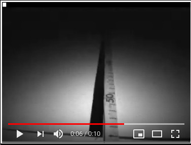
Option "--shutter 10000" sets exposure to 1/100 second. It is needed to see clear frames:
I wanted to show the video here, and I wanted to be able to show details.
Therefore I slowed it down by factor 3.
Unfortunately the generated 1920x1080 animated .gif is 107MB in size.
So while creating the .gif I scaled down by factor 6 to 320x180, with only 3.5MB size:
I think the speed should suffice for tracking pendulum -- origianl speed is 3 times faster.
And it is far more than needed when tracking real airplane in sky.
Next step is to determine for pendulum, how many pixels in generated frame correspond to a single stepper motor step up, down, left and right.
larryd:
Acrylic would make your assembly more flexible and robust.
Sure, but I have no experience with acrylic.
I do have a long history of connecting things by just superglueing them together.
And I have learned that superglued motor can withstand even heavy vibrations with high forces
[although sometimes big Lego wheel fixated with bullet on outrunner motor shaft escaped, see 90fps slowmo near camera hit ]: https://forum.arduino.cc/index.php?topic=331722.msg3338067#msg3338067
I looked at aliexpress and amazon for "pan tilt bracket" and only found servo PT system brackets. Seems that no one else uses stepper motors as I do.
HermannSW:
Based on all the code I have already, I would expect automatic centering of video on swinging red ball while recording video tomorrow (1920x1080@30fps and 640x480@90fps).
That was a bit too optimistic, although I made huge progress.
Further development of airplane tracking will be posted in this posting and following: https://www.raspberrypi.org/forums/viewtopic.php?f=43&t=252176&p=1566603#p1566603
I will report back here if pendulum ball tracking works and show an automatically centered video.
I added a 2nd heuristic on top of 1st and get a smooth moving blue point in "airplane".
I slowed down 90fps video by factor 30 for easy inspection.
This is animation with graphical debugging, see posting for details:
P.S:
Stepper motor does not seem to loose any steps at 0.8ms/step speed, 10 far moving repeats:
I just learned in another thread that powering both 28BYJ-48 stepper motors directly from Arduino 5V rail with half-stepping (4096 steps per revolution) draws 2×200mA, while an USB powered Arduino Uno does provide 450mA on 5V rail. So doing what I did, powering stepper PT camera system compeletly from Arduino Uno is safe! https://forum.arduino.cc/index.php?topic=648859.msg4377804#msg4377804
To be more precise on building instructions, this is the central superglue connection between the two 28BYJ-48 stepper motors [feels like the motor shaft was built for exactly that ;-)]:
I did complete the OpenScad modelling by adding Raspberry camera as well as wood base.
I learned how to pass an argument (angle) to "StepMotor28BYJ(-45)" module, the share link: https://tinyurl.com/t7kyfug
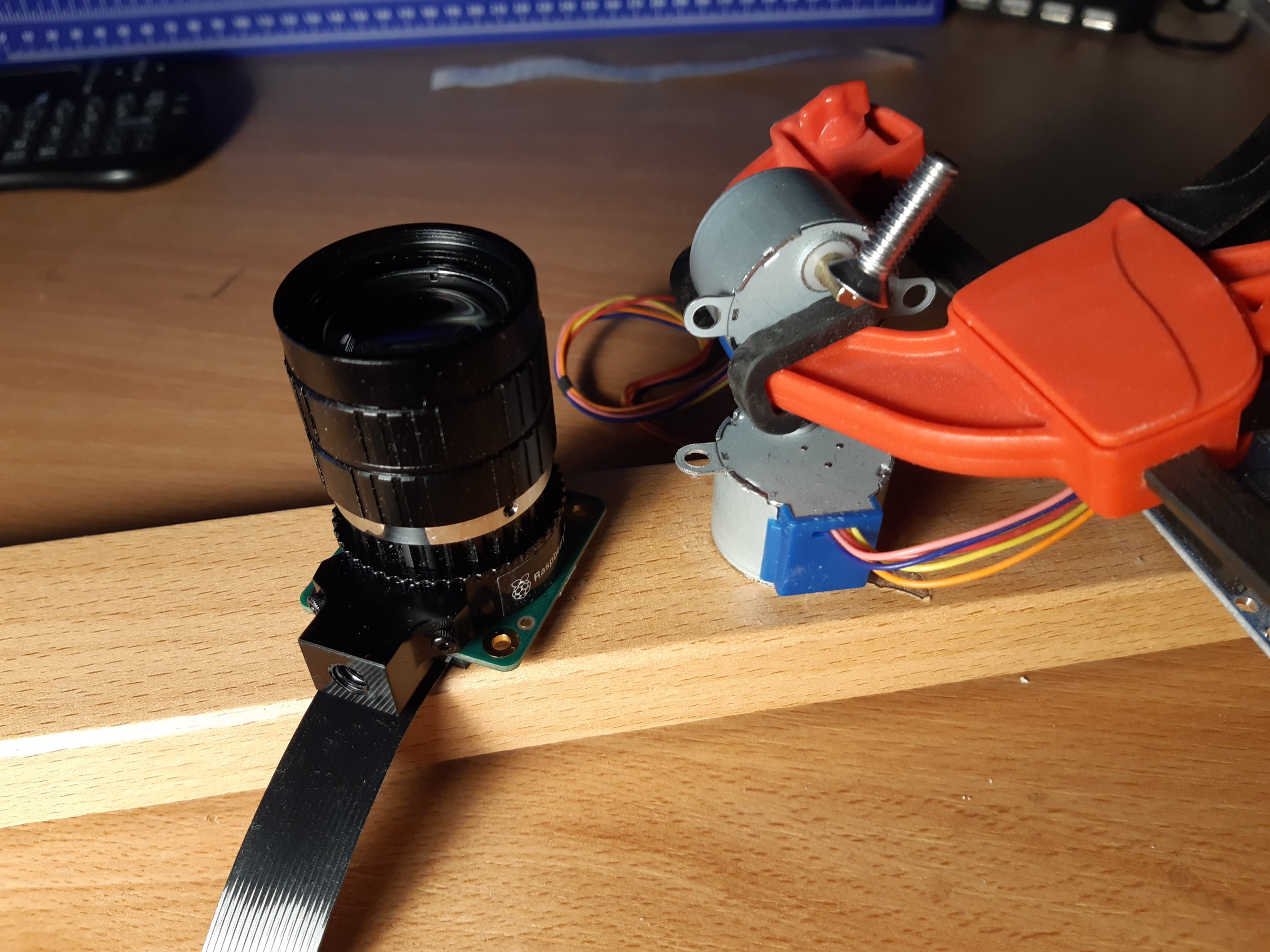
Today I played with Raspberry HQ camera and C-mount 35mm lens. Both together do weigh 109g together, with the top stepper 19g that is 128g in total. I was not sure whether superglue would be strong enough and tried.
HQ camera comes with tripod mount, and I measured M6 with micrometer. So in addition to the two stepper motors I superglued a M6 screw:
ballscrewbob:
Have you tried counter balancing some of these to offset the weight ?
No, thank you for that good idea!
That would really help for moving lens down.
For moving lens up there is less problems.
I just measured, and more than 12mm of M6x20 screw thread are not used.
So replacing M6x20 screw with M6x8 would bring everything closer to upper stepper motor shaft.
Then even 70° lens up should be possible:
That would be enough for capturing airplanes automatically centered
(on walk with dog I saw low flying airplane, and that reminded me on this project):
P.S:
The automatically centered airplane capturing project was planned as a pre-project for autonomous fast robot driving. I am much further with my raspcatbot project already, instead of real time locating airplane at sky, robot determines whether it is still on straight black line (sofar), processing 204 frames of ov7251 global shutter camera, and then does autonomous full stop from currently maximal seen 2.55m/s inhouse (robot can do 5m/s or 18km/h):
Until mounting 100g camera+lens onto stepper PT camera system on weekend, I was not aware that the Arduino code posted above produced jitter. The much less weight of the cameras I used before did not uncover that fact.
Today I just started the Arduino Uno with sketch from this posting above: https://forum.arduino.cc/index.php?topic=647703.msg4369656#msg4369656
I did let the joystick alone, no movements.
The jitter (in the analog reads?) is really heavy, this is 0.5s real time animated .gif loop from Raspberry HQ camera mode4 (1012x760) video capture at 60fps (that mode can capture up to 120fps), scaled to 1/3rd size:
So today I created modified sketch with jitter filter.
Jitter remained with threshold 5, 10 and 15. No jitter with 20, sketch uses threshold=25 to be on safe side:
#include <AccelStepper.h>

// ULN2003
AccelStepper stepper(AccelStepper::HALF4WIRE, 2, 4, 3, 5);
AccelStepper stepper2(AccelStepper::HALF4WIRE, 8, 10, 9, 11);

#define thr 25

void setup()
{
  stepper.setMaxSpeed(800);
  stepper.setAcceleration(250);
  stepper2.setMaxSpeed(800);
  stepper2.setAcceleration(250);
}

void loop()
{
  int x = 2*(analogRead(A1)-512);
  int y = -2*(analogRead(A0)-512);
  int cx = stepper.currentPosition();
  int cy = stepper2.currentPosition();

  if ((abs(x-cx) > thr) || (abs(y-cy) > thr))
  {
    stepper.moveTo(x);
    stepper2.moveTo(y);
  }

  stepper.run();
  stepper2.run();
}
I just measured, 35mm C-mount lens plus CStoC mount weight is 77.9g, while 300mm lens plus a CStoM12 adapter weight is 22.7g, that is 55g less weight.
In the posting pointed to above I have calculated that 80% of moon will cover full width (4056 pixel) of 12MP HQ camera photo, so moon can be viewed partially(!) only.