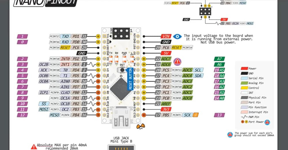
I confirmed that my two identical oled modules are in good working order by connection to an Elegoo Arduino UNO R3.
My wiring diagram, sketch and photo of the result are attached.
I still can't get either of my oleds working with either of my BLE 33s. I always get a screen of randomly coloured pixels sometimes with a faint line of mostly green pixels.
Here is a summary of what I know/have tried:
1)I've tried both my identical oled displays with my two BLE 33s. Still, random coloured pixels.
2)I've tried powering the display with 3.3V from the BLE 33, 5V from an external supply and 5V from the BLE 33 after shorting Vusb. Still, random coloured pixels.
3)I've successfully tested both of my BLE 33s with a Blinky example and an example that reads the onboard accelerometers.
4)I've checked the wiring diagram, wiring and continuity of connections with a multimeter many times.
5)I've checked that the pin numbers in the sketch match the wiring many times.
6)I've tried both a solderless and soldered breadboard. Still, random coloured pixels.
-
David P. has tried the same assembly and sketch with success. Thank you very much for doing that.
-
As just mentioned, both of my oleds work with an Elegoo UNO Rev 3.
9)I've tried two different USB cables.
10)All libraries are up to date.
I thought that I might be able to get use of a logic analyzer but no luck.
The only thing that I can imagine, as a beginner, is that the SPI circuitry in both of my BLE 33s is damaged but I think that this is extremely unlikely. But, I have ordered another BLE 33 which will arrive in a few days, i.e. during the week of 11 July 2022.
I'm a beginner doing this as a retirement project so I'm more interested in learning rather than obtaining a quick solution. So, any additional suggestions would be appreciated. I've got the time to try anything.
// Screen dimensions for 1.5" x 1.5" display
#define SCREEN_WIDTH 128
#define SCREEN_HEIGHT 128
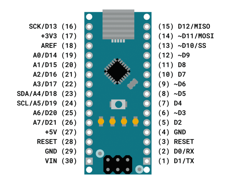
// Pin definitions
//#define SCLK_PIN 16
//#define MOSI_PIN 14
#define CS_PIN 13
#define DC_PIN 10
#define RST_PIN 11
// Colour definitions
#define BLACK 0x0000
#define BLUE 0x001F
#define RED 0xF800
#define GREEN 0x07E0
#define CYAN 0x07FF
#define MAGENTA 0xF81F
#define YELLOW 0xFFE0
#define WHITE 0xFFFF
// Libraries
#include <Adafruit_GFX.h>
#include <Adafruit_SSD1351.h>
#include <SPI.h>
// Create SSD1351 object
Adafruit_SSD1351 tft = Adafruit_SSD1351(SCREEN_WIDTH, SCREEN_HEIGHT, &SPI, CS_PIN, DC_PIN, RST_PIN);
void setup(void) {
tft.begin();
lcdTestPattern();
}
void loop() {
//do nothing
}
void lcdTestPattern(void)
{
static const uint16_t PROGMEM colors[] =
{ RED, YELLOW, GREEN, CYAN, BLUE, MAGENTA, BLACK, WHITE };
for(uint8_t c=0; c<8; c++) {
tft.fillRect(0, tft.height() * c / 8, tft.width(), tft.height() / 8,
pgm_read_word(&colors[c]));
}
}