4x4x4 Led Cube Guidance

Hi everyone. I've been wanting to make an Led cube for a few months now, but haven't actually made anything with an Arduino before. I understand how the cube itself will be made, but I have a few questions about the connections.

The way I understand it, each column will be connected an Arduino pin with a resistor in between. Each level will need to be hooked to a transistor, which will connect each respective level to the ground on the Arduino, and controlled by separate pins.

Assuming that's right, how is it all powered? Do the column pins themselves provide it? Is an external power source needed?

Thanks for putting up with me!

Draw up a schematic of what you are connecting.
If done correctly and your software multplexing is done correctly, then you could get away with driving 4 LEDs high on 4 columns from arduino while you pulled 1 row low with a ULN2803 controlled by arduino, and work your way across the 4 rows, then jumped to next level and worked across the 4 rows, then the 3rd & 4th.
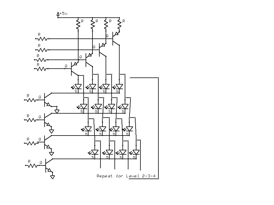
Picture this:
Level 1

C C C C
a b c d R1
e f g h R2
i j k l R3
m n o p R4

Level 2

C C C C
a b c d R5
e f g h R6
i j k l R7
m n o p R8

Level 3

C C C C
a b c d R9
e f g h R10
i j k l R11
m n o p R12

Level 4

C C C C
a b c d R13
e f g h R14
i j k l R15
m n o p R16

The Cs are your arduino high outputs.
The Rs are your ULN2803 current sinks - the lows. You need 2 devices.
So as long as you only have 1 R low at a time, each Arduino High output will only Source up to 20mA (controlled by the resistor), and each ULN2803 will sink up to 80mA when on, but only one at a time.
So your code will set the Cs, drive an R on, then off.
Set the Cs, drive an R on, then off.

Or, drive an R, turn Cs on. Turn Cs off.
Next R, turn Cs on, Turn Cs off.

Never turn 2 Rs on, that will really stress the Arduino C outpout. 3 will likely fatally damage it.

Another option is to have Arduino control a PNP transistor as the current source.

Options - use shift register with ULN2803 on output, free up more pins & seperate the Cs, maybe have 2 sets on at once.
Or possibly all 4, with seperate pins driving each set of columns, and clever shifting (needs 2 pins, maybe 3) to have R1,5,9,13 on, then 2,6,10,14.

Hmm...you mentioned using transistors. Can I use 16 transistors controlled by the digital outs and a few analogs used as digital to connect an external power source to each column? Then I wouldn't need to worry about damaging the Arduino, right?

"Can I use 16 transistors controlled by the digital outs and a few analogs used as digital to connect an external power source to each column?"

That's pretty much what I said. Use all 20 pins, D0-D13 and D14-D19 (A0-A5).
16 cathode drivers can be 16 discrete NPN transisters, or use 2 ULN2803, all packaged up nice & neat with base current limit resistors built in.
For the columns, you want a PNP from 5V to a column. Or a P-channel logic level MOSFET.

Ok, so the ULN2803 is essentially 8 transistors packaged together? (Sorry, new to this all...)

As for the columns, what is the difference between using a PNP or MOSFET?

ULN2803, pretty much. Go to ti.com and look at its datasheet.
PNP vs P-Channel MOSFET, same functionality, built differently electronically.
Do some reading at wikipedia, see what you can glean ...

Alright. Thanks for your help Crossroads!

Glad to help.
Hardware here is pretty straightforward, trickier part will be the coding to come up with patterns & stuff.

I haven't even gotten to there yet...just wanna be sure to get the hardware right!