This topic has been covered a little before, but I am looking for more basic information than I have been able to find on the Arduino Forum. This post from the archives covers wiring an 5 x 7 LED matrix: http://forum.arduino.cc/index.php/topic,25643.0.html
I have been trying to wire it up to work with the Arduino. Unfortunately, I am from a programming and art background, not an electronics one, and I am stumped at the earliest point. I am really unsure how to wire this matrix to and from an Arduino, and from which pin a ground should go. From testing (as per the forum post mentioned above) I have identified the cathodes in the pins and which row each cathode corresponds to. The columns light when I place power against the remaining pins (7 of these). What I am completely missing is what order power needs to enter and leave this matrix, and how each row/column should be connected to gain full control over the matrix. If I could even get a diagram or an explanation of how to light all of the LEDs at once that would be something, as I could whittle it down from there. But at the minute the best I can do is get one or two LEDs to light up while feeding in power from a 5v battery.
Also, as the schematic in the PDF above makes little or no sense to me, I have been using a 1k Ohm resistor to avoid blowing the bulbs, with 5V power source. If anyone has any advice on what power source/resistor would work best with these that would also be appreciated.
Hope you can help and thanks in advance! Apologies for my lack of electronic know-how.
finansh
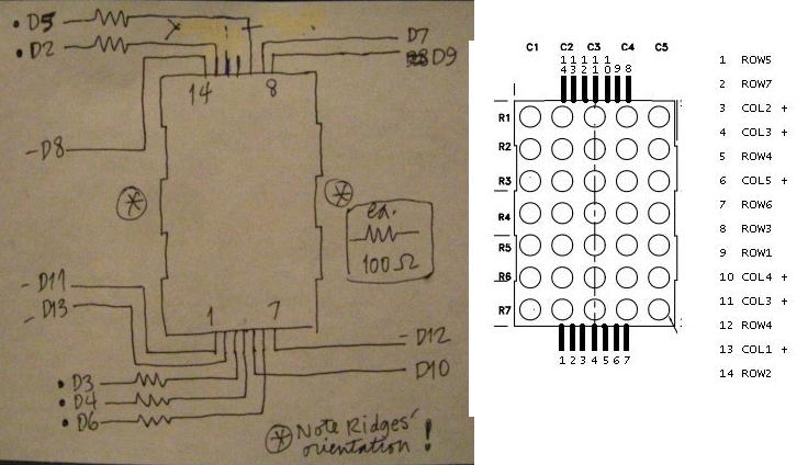
I will try to give you a little help to understand the internal wiring and pin numbering of the LED matrix to the best of my ability. Firstly you have to identify which is pin 1. I have an 8 x 8 matrix here and when I turn it over to the back it has the number 1 printed next to the bottom right hand pin ( this is with a full row of pins at the top and a full row at the bottom. Presumably in your case you will have a row of 7 pins and a row of 5 pins (attached as pic 1) How the pins are laid out is not that important but you need to work out which is pin 1 and then all the other pin numbers “flow” from there following these general conventions.
The important point is that the pin numbers run consecutively across on one row and then back in the opposite direction in the other row. This is generally a widely followed convention in electronics re the pin numbering of many different components. Then if you look at the diagram from the PDF you attached (attached as pic2)
The pair of diodes (LED’s) circled in red have to be connected in the correct way to light because they have polarity, which means that you have to connect the positive to the anode (the flat side of the triangle section of the diode (LED) symbol and the negative to the cathode (the side of the LED symbol that has the line across the axis of the symbol that intersects with the apex of the triangle (attached as pic3)
So to light the LED’s circled in red in Pic 2, you need to connect positive to pin 6 (anode) and negative (cathode) to pin 9
Likewise to light the LED’s circled in green at the top left of Pic 2 you connect positive (anode) to Pin 13 and negative (cathode) to Pin 9
As far as the resistor to use I suspect that as per halley’s advice here at the previous post you referenced
a 1K ohm resistor should be ok but you need to calculate the correct value based of the electrical specifications of the particulars LED’s in the matrix. Better too high a value than too low to avoid damage to the LED’s and later on damage to the Arduino itself..
Once you understand how to light any particular LED in the matrix it is then a matter of what you want to display on the matrix and how you implement that. That is when the fun begins, but believe me the people here are always willing to help enthusiastic newcomers. Good luck Pedro.
You asked how to get all the dots lit. Short answer is: you don't! Instead, you light one entire row (or one entire column, its up to you). After a short pause, you then you move to the next row and so on until each row has been individually lit for the same short time. Then repeat. Do this fast enough, perhaps 50 times per second, and it will appear to the human eye that all the dots are lit. This technique is called multiplexing.
Resistor values: you need just a couple of figures from that confusing data sheet, and a formula called Ohm's Law. R = V / I where R is the resistor value, V is the voltage across it and I is the current flowing through it. We will use the law on the resistor, not the diodes in the matrix.
The important figures from the data sheet are the Forward Voltage (Vf) and typical current (I typ) of the dots. The Vf is 4.0V. This is a surprisingly high figure, until you realise that each dot in this particular matrix has two LEDs, and may present some challenges later. The typical current is 20mA (maximum continuous is 30mA, but 20 will do for now).
So the dots need 4V to run, but your power supply is 5V. We need to get rid of 1 Volt, and this is what the resistor does for us. The same current will flow through both the resistor and the dot. The dot will use 4V and we want the remaining 1V to be used ("dropped") by the resistor. So, using Ohm's law, what should the resistor's value be?
int speed = 500;
byte idx;
byte colidx;
byte colsel [5] = {2,3,4,5,6};
byte rowsel [7] = {7,8,9,10,11,12,13};

void setup ()
{
  for (idx=2; idx < 7; idx++) // prep COLs
  {
    pinMode (idx,OUTPUT);
    digitalWrite (idx,LOW);  // COL off
  }
  for (idx=7; idx < 14; idx++) // prep ROWs
  {
    pinMode (idx,OUTPUT);
    digitalWrite (idx,HIGH);  // ROW off
  }
}

void loop ()
{
  for(colidx=0; colidx < 8; colidx++)
  {
    digitalWrite(colsel[colidx],HIGH); // col on
    for(idx=0; idx < 5; idx++)
    {
      digitalWrite(rowsel[idx],LOW); // on
      delay(speed);
      digitalWrite(rowsel[idx],HIGH); // off
    }
    digitalWrite(colsel[colidx],LOW); // col off
  }
}
If/When you want it to go faster, so that it looks like they're all on, make the variable speed a smaller number.
Running this big dude for brighter output will require more circuitry.
To me, sometimes, you have to, well, - "throw a dog a bone." [no offence]
If he comes back and questions whether the resistors are "really necessary" - then you lower the boom. ]