5M LED strip will not fully display all colours simultaneously [SOLVED]

For my first proper arduino project I wanted something that would start simple and get a little more difficult. I have some experience with electronics and a fair grasp of the language, so I figured I'd first control an RGB strip with it, then add bluetooth connectivity.
So far I'm struggling with merely controlling an rgb strip.

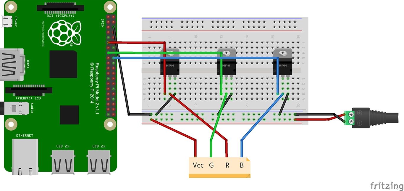
I've got an UNO, set up like this, but replace the pi with an UNO and the 12v dc adapter with a 9v battery and 2 AA1.5v cells in series to get 12v (This is only temporary.) Red is connected to pin 3, green to pin 5, and blue to pin 6.

If I output rgb 255,255,255 (white) I get what is visually the same as 255,0,0 (pure red)
If I output 0,255,255 I get the same result as 0,255,0 (pure green)
If I output 0,0,255 I get the correct pure blue, 0,0,255.

I've figured out through trial and error that to get what looks like white i can input (255/8,255/4,255), and to get secondary colours i can divide the red value by 4 and the green value by two, but it also seems to work with red/8 and green/4.

I'm sure there's something I'm missing here, or should be accounting for but for whatever reasons I'm missing it entirely.

If it helps, here is one of the codes I was using to control it:

#define REDPIN 3
#define GREENPIN 5
#define BLUEPIN 6

#define FADESPEED 10     // make this higher to slow down

const double redMultiplier = 0.12;
const double greenMultiplier = 0.5;
const double blueMultiplier = 1;

double brightnessMultiplier = 1;

int r = 255;
int g = 0;
int b = 255;

int rVal = 0;
int gVal = 0;
int bVal = 0;

// the setup function runs once when you press reset or power the board
void setup() {
  pinMode(REDPIN, OUTPUT);
  pinMode(GREENPIN, OUTPUT);
  pinMode(BLUEPIN, OUTPUT);
}

// the loop function runs over and over again forever
 
void loop() {

  rVal = r*redMultiplier*brightnessMultiplier;
  gVal = g*greenMultiplier*brightnessMultiplier;
  bVal = b*blueMultiplier*brightnessMultiplier;

  analogWrite(REDPIN,rVal);
  analogWrite(GREENPIN,gVal);
  analogWrite(BLUEPIN,bVal);
}

And also the links to some of the components I'm using:

https://www.amazon.co.uk/gp/product/B00VY3ZLMO/ref=oh_aui_detailpage_o02_s00?ie=UTF8&psc=1
https://www.amazon.co.uk/gp/product/B01MPWHTF6/ref=oh_aui_detailpage_o03_s00?ie=UTF8&psc=1
https://www.amazon.co.uk/gp/product/B071VXRQYR/ref=oh_aui_detailpage_o03_s00?ie=UTF8&psc=1

Thanks in advance.

I'm sure there's something I'm missing here, or should be accounting for but for whatever reasons I'm missing it entirely.

  1. Your diagram shows you have NPN transistors but you have no base resistors.

  2. You are mixing floating point and integer numbers.

  3. Any analog write above 255 acts like it starts again at zero. So 256 acts as zero, 257 acts like 1 and so on. This repeats again at 512 and at every 256 interval after that.

a 9v battery and 2 AA1.5v cells in series to get 12v

I think this may be your problem. I assume the 9V battery is PP3 size? Those are the only 9V type that are commonly available these days. They are used in smoke detectors. And frankly, that is the only thing they are suitable for.

The problem with PP3 is that they have a high internal resistance. This means that if you draw any more than a small current, the battery's output voltage drops significantly. I am not talking about an exhausted battery, even a fresh PP3 will do this.

Your strip will draw a lot of current, especially at 255,255,255. This will mean the PP3's voltage will drop and the blue and green LEDs will not light much if at all, leaving only the red LEDs lit.

If you reduce the pwm down, less current is drawn, the PP3's voltage will drop less and as you have found, you can, by trial and error, get something close to white.

So the answer could be to get rid of that PP3. Use 8xAA, or a small 12V SLA battery perhaps. Or a 12V PSU/adaptor, of course.

PaulRB:
The problem with PP3 is that they have a high internal resistance. This means that if you draw any more than a small current, the battery's output voltage drops significantly. I am not talking about an exhausted battery, even a fresh PP3 will do this.

Good to hear that it could be something this simple - I have a 12v adapter on the way, so I guess I'll just wait until then-might try AAs but I dont have that many holders (:

Grumpy_Mike:

  1. Your diagram shows you have NPN transistors but you have no base resistors.

Thanks for the suggestion, but I'm using mosfets, not npn transistors - unless these are the same thing and I don't know about it. Other than that, I'm not having issues with the colours looping or issues with floats and ints.

Thanks for the suggestion, but I'm using mosfets, not npn transistors.

Then why the hell did you use NPN transistors in that Frizing layout diagram!

That is why these things are hated here. There is NO point in drawing a layout and then have the wrong components in it. It is just lying and wastes everone's time.

This is how you post links. Code tags are no good for links, as you used before, they can't be clicked. The forum guide in the sticky post will tell you about these things.

Uno. Humph. Everybody recommends them to beginners, even when they know the beginner wants to use a breadboard...

https://www.amazon.co.uk/gp/product/B01MPWHTF6/ref=oh_aui_detailpage_o03_s00?ie=UTF8&psc=1
So, 300 LEDs, which of course is actually 900 LEDs as each "led" is a red, a green and a blue led. At 20mA each, the whole strip could need 6A @ 12V. What's the current capacity of the PSU you ordered?

Also, you can't put 6A through a breadboard. You will melt it! If you don't mind cutting your strip, make a short strip of no more than 50 LEDs to use while you are prototyping on breadboard. If you solder-up the final circuit on stripboard/veroboard, lay bare wire along the copper strips where the high currents will flow, and cover the whole length with a generous coating of solder.

RFP30N06LE. Looks like a good choice. Max gate threshold voltage of 2V. On-resistance of 47 milli-ohm. Should stay reasonably cool. If they get too hot to touch, you will need heatsinks, but they probably won't.

Thanks for all the advice - the power supply arrived today and all works well.
As for the diagram - apologies, it's merely a guide I followed which instructed the use of mosfets - the image isn't mine.
Thanks also for the advice on the breadboard/stripboard, I had no idea.