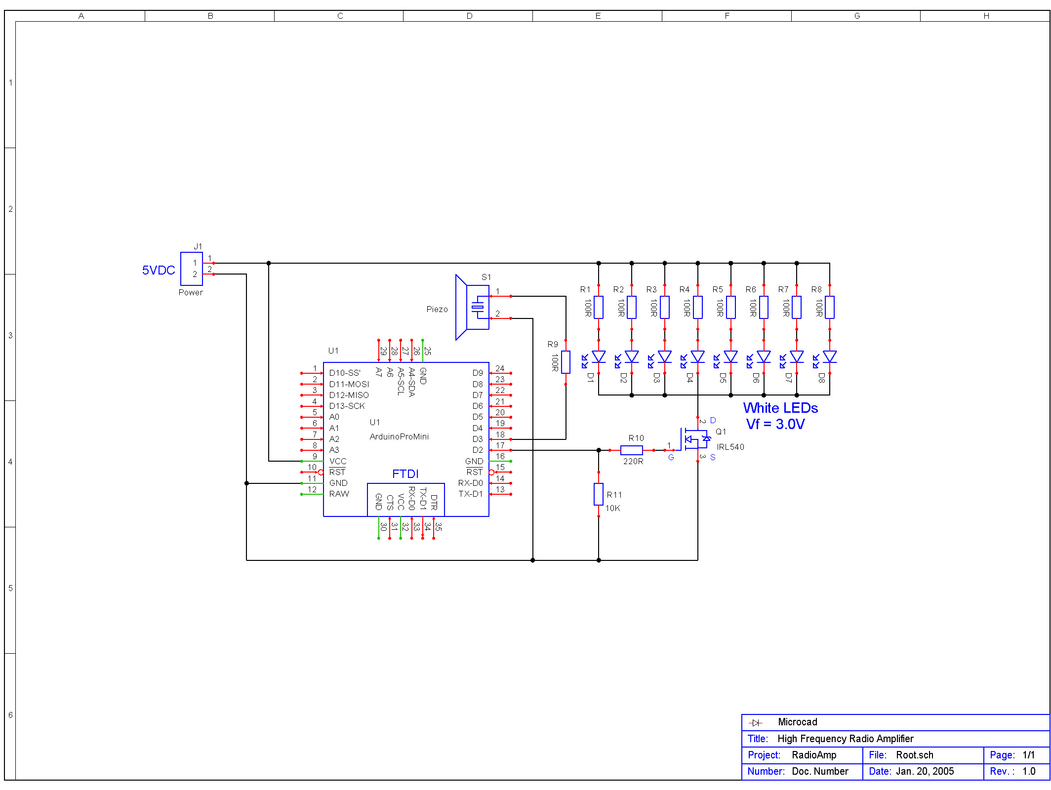
Thanks. Actually... I only need to run ordinary old LEDs like this ebay.com.au/itm/20x-5mm-WARM-WHITE-LED-Clear-Light-Emitting-Diode-Pack-AUS-STOCK/180876304882
and they only draw 20mA so that's not a big deal is it? And I could get the LED array out of a torch right?
A mini torch has 9 LEDs so that's still only 180mA.
Basically I need a light to switch on and off 40 times a second. I don't know how bright it needs to be, but bright enough that you'd be aware of it. Could I try it with 1 LED and add more until I think its bright enough?
I want it to be neatly contained in a box with an AC/DC power supply or a USB cable plugged into a wall charger.
I also want to add a piezo buzzer going on and off at 40Hz, like the lights. In the experiments with mice, there was a greater effect when sound and light were combined.
Indeed you are confused, and it is most unfortunate.
chibi-arduino:
Can I just use, say, a 9V AC-DC power supply plugged into the barrel connector? Then can I draw voltage from the 5V pin to power the LED strip?
No. You can't.
chibi-arduino:
Or do I have to use the VIN and an external power supply? And in that case, how do I actually connect the VIN to power from the wall?
Equally bad.
The "barrel connector" and "Vin" feed the regulator on board the UNO. This regulator - with virtually no heatsink - is more-or-less capable of powering the two processors on the board. Perhaps a few LEDs requiring 20 mA each. But that's it. You do not use it as a means to power 5 V devices which draw any significant current; it will overheat and shut down (hopefully reversibly ).
In the video you cite, the UNO variant is powered from the USB connector which is capable of providing something like 500 mA through to the "5V" pin. It is limited by a "polyfuse" to a nominal 500 mA but will generally tolerate a little more. The 3 W LED would presumably draw 700 mA or more (if actually powered to 3 W which it most probably is not) and your 8 NeoPixels up to 480 mA.
chibi-arduino:
Basically I need a light to switch on and off 40 times a second. I don't know how bright it needs to be, but bright enough that you'd be aware of it.
At 40 times per second, the flicker is usually not able to be discerned. So it appears continuous.
If it appears continuous, then that means the signal from the eye to the optic nerve is itself continuous, so there is no reason to suspect it would have any other effect on the brain than - a continuous light. Note that televisions traditionally flickered at 50 or 60 Hz, and I'm not sure whether anyone ever determined a benefit to cognition from watching them.
current = 3w/3v(Vf) =~1A <———<<<<< She is over taxing the Arduino!!!
“ how is it possible for her to power a 3w led from the arduino 5V pin??“
It appears each module has a MOSFET transistor on the PCB to drive the high wattage LED.
Paul__B:
At 40 times per second, the flicker is usually not able to be discerned. So it appears continuous.
If it appears continuous, then that means the signal from the eye to the optic nerve is itself continuous, so there is no reason to suspect it would have any other effect on the brain than - a continuous light. Note that televisions traditionally flickered at 50 or 60 Hz, and I'm not sure whether anyone ever determined a benefit to cognition from watching them.
The therapeutic effects of 40Hz flicker on mouse brains was reported in Nature, more than once. They found that 40Hz, and only 40Hz, produced a significant reduction (more than 50%) of amyloid plaque. They also measured the stimulation of 40Hz gamma waves when the brain was stimulated in that way. Most of the plaque reduction was in the visual cortex. Even the researchers were very surprised.
Sometimes what seems logical and rational is not the same as science.