I have read through what I can find on this topic.
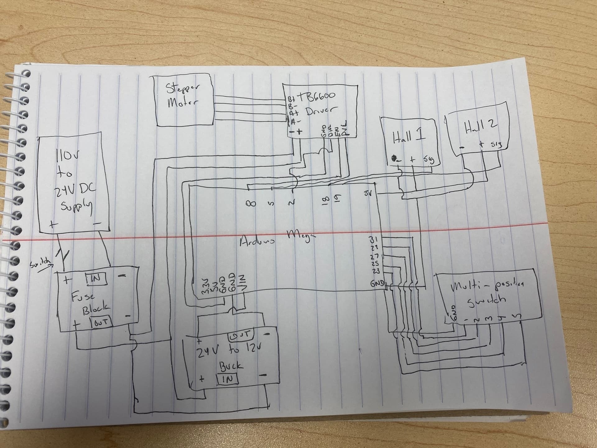
I am only getting 3.3V from the 5V pin when powered by external 12V power source using the VIN pin. If I plug in to the computer, the 5V pin supplies 5V. Rough wiring diagram below. All voltages are what they should be except for the 5V out.
What made me find this is that my program will not run without being plugged into the computer.
Are the Hall sensors the only things connected to the mystery Arduino 5V?
Please post a complete schematic. Hand drawn, photographed and posted is fine. Include all pin names/numbers, components, their part numbers and/or values and power supplies.
The on board 5V regulator is not heat sinked so will supply limited current before it overheats and shuts down. The amount of current depends on the voltage input to Vin or the power jack. The higher the voltage the less current can by supplied. To output 5V from a 12V input the regulator must drop 7V. The maximum power dissipation for the (not heat sinked) regulator is about 1W. So that means that the maximum current is about 142mA [1W / (12V-5V)]. The Mega takes around 50mA that leaves 90mA (at best) for the rest. That is why it is not recommended to use 12V input to Vin. It is much better to drop the higher voltage to 5V and apply that 5V to the 5V pin of the Arduino, bypassing the weak 5V regulator.
To close this, I ordered a 24v to 5v buck and swapped it with the 24v to 12v. I plugged the lead into the 5V pin and everything is working as it should now.