5x5x5 RGB Color Cube
That is the how to i followed with some changes.
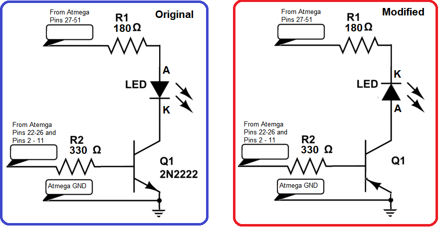
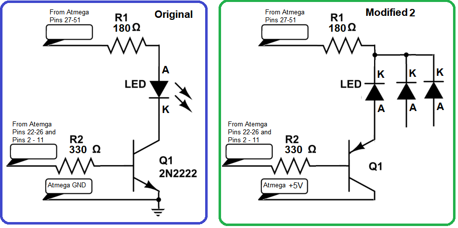
I have used not common anode leds but common cathode leds.
And not NPN transistors but PNP transistors.
I have the problem after some coding changes (common anode to cathode) that all the leds are on during the loop and they must be off.
in the following code there should only be one led on and the rest off
/* This is for a 5x5x5 RGB LED cube running on an Arduino MEGA
   This is the full show with 16 different animations
   It takes 5 minutes to run through before repeating
*/

byte mask; // used by BAM refresh routine
volatile byte cube[5][5][5][3]; // where content of the cube is stored by color

// Color Management
// these are colors that can be specified by GetColor() routine
// calling this routine from 1 to 42 gives you a 42 step rainbow palette
#define White 43
#define Black 0
#define Red 1
#define Orange 4
#define Yellow 9
#define Green 15
#define Aqua 20
#define Blue 29
#define Purple 34
byte mycolor; // an evolving color
byte myred, mygreen, myblue; // components of a color
const byte color[44][3] PROGMEM = { // the color palette table
    {0, 0, 0}, //Black
    {7, 0, 0}, {7, 1, 0}, {6, 1, 0}, {6, 2, 0}, {5, 2, 0}, {5, 3, 0}, {4, 3, 0}, {4, 4, 0}, {3, 4, 0}, {3, 5, 0}, {2, 5, 0}, {2, 6, 0}, {1, 6, 0}, {1, 7, 0}, // Red to Green
    {0, 7, 0}, {0, 7, 1}, {0, 6, 1}, {0, 6, 2}, {0, 5, 2}, {0, 5, 3}, {0, 4, 3}, {0, 4, 4}, {0, 3, 4}, {0, 3, 5}, {0, 2, 5}, {0, 2, 6}, {0, 1, 6}, {0, 1, 7}, // Green to Blue
    {0, 0, 7}, {1, 0, 7}, {1, 0, 6}, {2, 0, 6}, {2, 0, 5}, {3, 0, 5}, {3, 0, 4}, {4, 0, 4}, {4, 0, 3}, {5, 0, 3}, {5, 0, 2}, {6, 0, 2}, {6, 0, 1}, {7, 0, 1}, // Blue to Red
    {7, 7, 7} // White
};

// *********************************Setup ******************************
void setup() {
    // set all pins to output and initialize low
    for (int x = 2; x < 12; x++) { // Green and Blue anode pins
        pinMode(x, OUTPUT);
        digitalWrite(x, HIGH); // Common Cathode: Change to HIGH
    }
    for (int x = 22; x < 52; x++) { // Red anode (22-26) and Cathode pins
        pinMode(x, OUTPUT);
        digitalWrite(x, HIGH); // Common Cathode: Change to HIGH
    }

    // TIMER 1 Setup for interrupt frequency 67 Hz = 15 ms refresh rate
    // Refresh actually takes 13 ms, so the processor spends 87% of its time refreshing

    cli(); // stop interrupts
    TCCR1A = 0; // set the entire TCCR1A register to 0
    TCCR1B = 0; // same for TCCR1B
    TCNT1 = 0; // initialize counter value to 0
    // set compare match register for 67.00167504187604 Hz increments
    OCR1A = 29849; // = 16000000 / (8 * 67.00167504187604) - 1 (must be <65536)
    // turn on CTC mode
    TCCR1B |= (1 << WGM12);
    // Set CS12, CS11, and CS10 bits for 8 prescaler
    TCCR1B |= (0 << CS12) | (1 << CS11) | (0 << CS10);
    // enable timer compare interrupt
    TIMSK1 |= (1 << OCIE1A);
    sei(); // allow interrupts
}
// ***************************** End Setup ************************************

// *****************************  Main Loop ************************************
void loop() {
  for (int z = 0; z < 5; z++) {
    for (int x = 0; x < 5; x++) {
      for (int y = 0; y < 5; y++) {
        LED(x, y, z, Red);
        delay(100);
        LED(x, y, z, Green);
        delay(100);
        LED(x, y, z, Blue);
        delay(100);
        LED(x, y, z, Black);
      }
    }
  }
}
// ***************************** End Main Loop *****************************************

// *******************************  Start of General Support Routines ************************

// this routine pushes the content of each layer down to the next
// then clears the top layer; the bottom layer fades away gradually
void copyDown() {
  for (int z = 0; z < 4; z++) {
    for (int x = 0; x < 5; x++) {
      for (int y = 0; y < 5; y++) {
        if (z == 0 && cube[x][y][z][0] > 0 || cube[x][y][z][1] > 0 || cube[x][y][z][2] > 0) {
          if (cube[x][y][z][0] > 0)cube[x][y][z][0]--;
          if (cube[x][y][z][1] > 0) cube[x][y][z][1]--;
          if (cube[x][y][z][2] > 0) cube[x][y][z][2]--;
        }
        else {
          for (int c = 0; c < 3; c++) {
            cube[x][y][z][c] = cube[x][y][z + 1][c];
          }
        }
      }
    }
  }
  for (int x = 0; x < 5; x++) {
    for (int y = 0; y < 5; y++) {
      for (int c = 0; c < 3; c++) {
        cube[x][y][4][c] = 0;
      }
    }
  }
}

// turns everything off
void clearCube() {
  memset(cube, 0, 375 * sizeof cube[0][0][0][0]);
}

// Sets intensity of all three colors of one LED to generate a specified color
// White=45  Black = 46  Red= 0; Green=15; Blue=30
void LED(byte x, byte y, byte z, byte color) {
  getColor(color);
  cube[x][y][z][0] = myred;
  cube[x][y][z][1] = mygreen;
  cube[x][y][z][2] = myblue;
}

// these next 6 subroutines provide the ability to turn red, green, or blue LEDs on independent of other colors
// used for moving colored panels through each other, etc.
void redON(int x, int y, int z) {
  cube[x][y][z][0] = 7;
}
void redOff(int x, int y, int z) {
  cube[x][y][z][0] = 0;
}
void greenON(int x, int y, int z) {
  cube[x][y][z][1] = 7;
}
void greenOff(int x, int y, int z) {
  cube[x][y][z][1] = 0;
}
void blueON(int x, int y, int z) {
  cube[x][y][z][2] = 7;
}
void blueOff(int x, int y, int z) {
  cube[x][y][z][2] = 0;
}

//  This routine generates 42 different colors around the color wheel using our 3 bit BAM
void getColor(int thecolor) {
  myred = pgm_read_byte_near(&color[thecolor][0]);
  mygreen = pgm_read_byte_near(&color[thecolor][1]);
  myblue = pgm_read_byte_near(&color[thecolor][2]);
}

// show cube for a multiples of 10 ms before clearing it.
void showCube(int mytime) {
  delay(10 * mytime);
  clearCube();
}

void pause() {  // pause between animations
  clearCube();
  delay(500);
}

// *******************************  End of General Support Routines ************************

// *******************************  Start of Refresh Timer Interrupt ************************
/* Timed Refresh Routine - Uses about 13 ms every 15 msec. Setup time (to configure anodes 45 times) is 2.5 ms, the other 10.5 ms
   are delays while LEDs are on.  This refresh routine uses BAM or bit angle modulation to control the intensity of each color
   This is 3 bit BAM, so the lowest three bits in the cube array represent a color intensity between 0 and 7.  We make 3 passes
   through the refresh routine first turning LEDs on for 100 microsec if the least significant bit is set.  Then we turn
   on LEDs for 200 microsec if the 2nd bit is set; finally we turn LEDs on for 400 microsec if third bit is set.
   This process is first done for red LEDs, then for green LEDs and then blue LEDs.  Anodes must be configured on or off for each
   color and each layer.  Direct port access is used for everything including selecting the cathode pins for layer and color.
   Altogether we must configure the 25 anode pins 45 times during each refresh - 3 bits BAM x 3 colors x 5 layers during each refresh.
*/
ISR(TIMER1_COMPA_vect) {
  // Sets the BAM time to 100 and doubles it twice, i.e. 100, 200, 400; I.E. 3 bit BAM
  for (int BAMtime = 100; BAMtime < 500; BAMtime = BAMtime << 1) {
    if (BAMtime == 100) mask = 0b00000001; // set mask to read least significant bit of color intensity
    else if (BAMtime == 200) mask = 0b00000010;
    else if (BAMtime == 400) mask = 0b00000100; // set mask to read most significant bit color intensity
    redCathodes(BAMtime);
    greenCathodes(BAMtime);
    blueCathodes(BAMtime);
  }
}
// turn on red LEDs for BAMtime (common cathode)
void redCathodes(int mytime) {
  configAnodes(0, 0);
  PORTH &= ~(1 << PORTH4);
  delayMicroseconds(mytime);
  PORTH |= (1 << PORTH4);
  configAnodes(0, 1);
  PORTH &= ~(1 << PORTH5);
  delayMicroseconds(mytime);
  PORTH |= (1 << PORTH5);
  configAnodes(0, 2);
  PORTH &= ~(1 << PORTH6);
  delayMicroseconds(mytime);
  PORTH |= (1 << PORTH6);
  configAnodes(0, 3);
  PORTB &= ~(1 << PORTB4);
  delayMicroseconds(mytime);
  PORTB |= (1 << PORTB4);
  configAnodes(0, 4);
  PORTB &= ~(1 << PORTB5);
  delayMicroseconds(mytime);
  PORTB |= (1 << PORTB5);
}

// turn on green LEDs for BAMtime (common cathode)
void greenCathodes(int mytime) {
  configAnodes(1, 0);
  PORTA &= ~(1 << PORTA0);
  delayMicroseconds(mytime);
  PORTA |= (1 << PORTA0);
  configAnodes(1, 1);
  PORTA &= ~(1 << PORTA1);
  delayMicroseconds(mytime);
  PORTA |= (1 << PORTA1);
  configAnodes(1, 2);
  PORTA &= ~(1 << PORTA2);
  delayMicroseconds(mytime);
  PORTA |= (1 << PORTA2);
  configAnodes(1, 3);
  PORTA &= ~(1 << PORTA3);
  delayMicroseconds(mytime);
  PORTA |= (1 << PORTA3);
  configAnodes(1, 4);
  PORTA &= ~(1 << PORTA4);
  delayMicroseconds(mytime);
  PORTA |= (1 << PORTA4);
}

// turn on blue LEDs for BAMtime (common cathode)
void blueCathodes(int mytime) {
  configAnodes(2, 0);
  PORTE &= ~(1 << PORTE4);
  delayMicroseconds(mytime);
  PORTE |= (1 << PORTE4);
  configAnodes(2, 1);
  PORTE &= ~(1 << PORTE5);
  delayMicroseconds(mytime);
  PORTE |= (1 << PORTE5);
  configAnodes(2, 2);
  PORTG &= ~(1 << PORTG5);
  delayMicroseconds(mytime);
  PORTG |= (1 << PORTG5);
  configAnodes(2, 3);
  PORTE &= ~(1 << PORTE3);
  delayMicroseconds(mytime);
  PORTE |= (1 << PORTE3);
  configAnodes(2, 4);
  PORTH &= ~(1 << PORTH3);
  delayMicroseconds(mytime);
  PORTH |= (1 << PORTH3);
}

// set the 25 anodes low for ON or high for OFF. We do this 45 times: 3 BAM times x 3 colors x 5 layers
void configAnodes(int color, int layer) {
  // inputs are color, layer, and mask (which is set up by BAM to match the bit we are selecting on for BAMtime
  // load the content of cube array for column 0 using direct port access
  if ((cube[0][0][layer][color] & mask) > 0) PORTL |= (1 << PORTL5); else PORTL &= ~(1 << PORTL5); // pin 44
  if ((cube[0][1][layer][color] & mask) > 0) PORTL |= (1 << PORTL6); else PORTL &= ~(1 << PORTL6); // pin 43
  if ((cube[0][2][layer][color] & mask) > 0) PORTL |= (1 << PORTL7); else PORTL &= ~(1 << PORTL7); // pin 42
  if ((cube[0][3][layer][color] & mask) > 0) PORTG |= (1 << PORTG0); else PORTG &= ~(1 << PORTG0); // pin 41
  if ((cube[0][4][layer][color] & mask) > 0) PORTG |= (1 << PORTG1); else PORTG &= ~(1 << PORTG1); // pin 40
  // load the content of cube() for column 1 using direct port access
  if ((cube[1][0][layer][color] & mask) > 0) PORTA |= (1 << PORTA5); else PORTA &= ~(1 << PORTA5); // pin 27
  if ((cube[1][1][layer][color] & mask) > 0) PORTD |= (1 << PORTD7); else PORTD &= ~(1 << PORTD7); // pin 38
  if ((cube[1][2][layer][color] & mask) > 0) PORTG |= (1 << PORTG2); else PORTG &= ~(1 << PORTG2); // pin 39
  if ((cube[1][3][layer][color] & mask) > 0) PORTB |= (1 << PORTB2); else PORTB &= ~(1 << PORTB2); // pin 51
  if ((cube[1][4][layer][color] & mask) > 0) PORTB |= (1 << PORTB3); else PORTB &= ~(1 << PORTB3); // pin 50
  // load the content of cube() for column 2 using direct port access
  if ((cube[2][0][layer][color] & mask) > 0) PORTC |= (1 << PORTC0); else PORTC &= ~(1 << PORTC0); // pin 37
  if ((cube[2][1][layer][color] & mask) > 0) PORTC |= (1 << PORTC1); else PORTC &= ~(1 << PORTC1); // pin 36
  if ((cube[2][2][layer][color] & mask) > 0) PORTC |= (1 << PORTC2); else PORTC &= ~(1 << PORTC2); // pin 35
  if ((cube[2][3][layer][color] & mask) > 0) PORTC |= (1 << PORTC3); else PORTC &= ~(1 << PORTC3); // pin 34
  if ((cube[2][4][layer][color] & mask) > 0) PORTC |= (1 << PORTC4); else PORTC &= ~(1 << PORTC4); // pin 33
  // load the content of cube() for column 3 using direct port access
  if ((cube[3][0][layer][color] & mask) > 0) PORTL |= (1 << PORTL0); else PORTL &= ~(1 << PORTL0); // pin 49
  if ((cube[3][1][layer][color] & mask) > 0) PORTL |= (1 << PORTL1); else PORTL &= ~(1 << PORTL1); // pin 48
  if ((cube[3][2][layer][color] & mask) > 0) PORTL |= (1 << PORTL2); else PORTL &= ~(1 << PORTL2); // pin 47
  if ((cube[3][3][layer][color] & mask) > 0) PORTL |= (1 << PORTL3); else PORTL &= ~(1 << PORTL3); // pin 46
  if ((cube[3][4][layer][color] & mask) > 0) PORTL |= (1 << PORTL4); else PORTL &= ~(1 << PORTL4); // pin 45
  // load the content of cube() for column 4 using direct port access
  if ((cube[4][0][layer][color] & mask) > 0) PORTC |= (1 << PORTC5); else PORTC &= ~(1 << PORTC5); // pin 32
  if ((cube[4][1][layer][color] & mask) > 0) PORTC |= (1 << PORTC6); else PORTC &= ~(1 << PORTC6); // pin 31
  if ((cube[4][2][layer][color] & mask) > 0) PORTC |= (1 << PORTC7); else PORTC &= ~(1 << PORTC7); // pin 30
  if ((cube[4][3][layer][color] & mask) > 0) PORTA |= (1 << PORTA7); else PORTA &= ~(1 << PORTA7); // pin 29
  if ((cube[4][4][layer][color] & mask) > 0) PORTA |= (1 << PORTA6); else PORTA &= ~(1 << PORTA6); // pin 28
}

// *******************************  End of Refresh Timer Interrupt ************************

