It is a very small footprint board that incorporates an Atmega 644 / 1284 MCU. I originally designed it because I love the Nano, but I needed more resources to run some OLED and TFT displays and was not satisifed with available alternatives. I could not find it on the market though it might have existed in the past (but without USB as far as I could see).
The design is a common and relatively simple one. The hard part in this project is the QFN assembly and the baking of the double sided board. So I will probably ask a chinese manufacturer to assemble them.
I will be glad to reading your constructive comments!
Backer #3 here. I've played with 1284 but only in DIP package. I had considered a Nano style board with USB, crystal, etc all in one package but the 44 pin TQFP is a bit big for a narrow breadboard friendly design and would end up more like a variant of UNO board with extra pins broken out. I can't hand solder the smaller package and I don't have the equipment for reflow soldering.
The icsp header in post #1 seems to have a non-standard pin out.
What else is broken out in the four pin group including sda and scl?
The Nano Every (4809 based) may give you some competition, although its megaAVR series 0 architecture makes it less easy to upgrade to from the original Nano.
Even an SMD version with uSD socket on it. 5V board, fully buffered 3.3V uSD socket.
Your choice of crystal too - 8, 16, 20 MHz, or overclock it you want the appropriate bootloader & library changes (Serial mostly I would guess).
ICSP pins are accessible on the regular header pins. FTDI header for code development/download, then remove it for your embedded system.
Put right angle pins on - square to plug in breadboard, or round machine pins to plug into a socket.
Or have them stick out sideways for a lower profile.
wilykat:
Backer #3 here. I've played with 1284 but only in DIP package. I had considered a Nano style board with USB, crystal, etc all in one package but the 44 pin TQFP is a bit big for a narrow breadboard friendly design and would end up more like a variant of UNO board with extra pins broken out. I can't hand solder the smaller package and I don't have the equipment for reflow soldering.
First, I would like to thank you VERY MUCH for supporting the project.
As you have experimented it is not so easy to do. I thought this project would be an easy one. It is certainly not very complex. A barebone. But the problem I had indeed is soldering the QFN part particularly since it has an EP and because I should use non lead solder paste. So even with a inox stencil and my customized T-962 oven I really had a hard time soledring the first prototypes.
Probably it has more flux in it and spreads better into the stencil holes and seems to wet better. It is still going to be one of the problems when doing tens of assemblies.
6v6gt:
The icsp header in post #1 seems to have a non-standard pin out.
What else is broken out in the four pin group including sda and scl?
The Nano Every (4809 based) may give you some competition, although its megaAVR series 0 architecture makes it less easy to upgrade to from the original Nano.
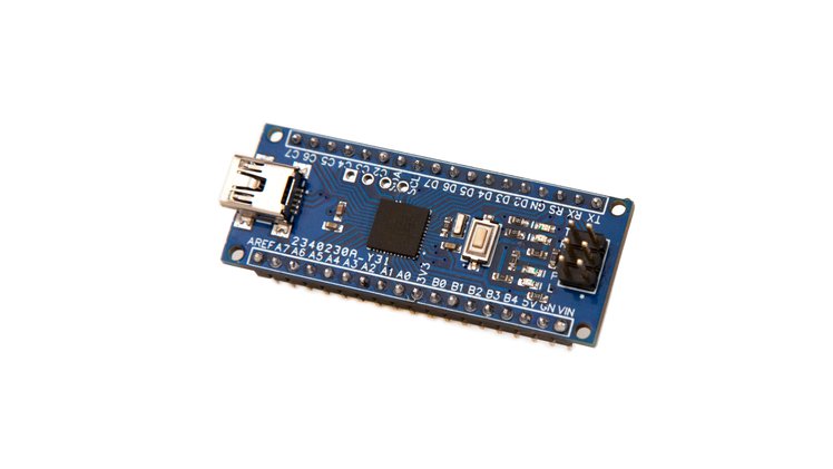
The connector is the same as one on the Nano. Here is a shot of both boards
The 4 pin connector is specifically to connect a 4 pin I2C oled module. Some modules might be cabled in reversed order since this is non-standard, but usually the pins are: GND, 5V, SCL, SDA.
Surely the Bobuino is a reference project! Narrow uses the MightyCore and I hope MCDude might include the Narrow variant next.
As you see I have been obsessed with compact boards. I did the PowMeter Shield Nano | Crowd Supply project and since I need to focus on some specific technologies because this knowledge field is quite large, the narrow project was attractive.
In your experience of the 644/1284 chips, did you encounter specific problems?
mrguen:
The connector is the same as one on the Nano. Here is a shot of both boards
The 4 pin connector is specifically to connect a 4 pin I2C oled module. Some modules might be cabled in reversed order since this is non-standard, but usually the pins are: GND, 5V, SCL, SDA.
OK. I've looked again. It does appear correct, although the header RESET pin is not marked. The arrow from the label you have marked as MOSI confused me because it goes through the RESET pin on the header and then, rather indistinctly, goes on through (correctly) to the MOSI pin.
I know the pinout from memory, because my normal technique for restarting an Arduino that has an ICSP header, but no reset button, is to touch a metal part between the reset pin and the ground pin. At first sight, I could not see how this would work with your pinout.
The "644/1284 Narrow" campaign is approaching its end. For now the goal is not reached. So if you would like to have this kind of device one day, it is the last call!