Looking to use 3 x7 segment LED displays - it’s been a while since I’ve done this , what is the best way to drive these ?
Last time I did , it was 74ls47, is there a dedicated multi segment chip , shift registers ???
Looking to use 3 x7 segment LED displays - it’s been a while since I’ve done this , what is the best way to drive these ?
Last time I did , it was 74ls47, is there a dedicated multi segment chip , shift registers ???
MAX7219.
a7
Nice one thx
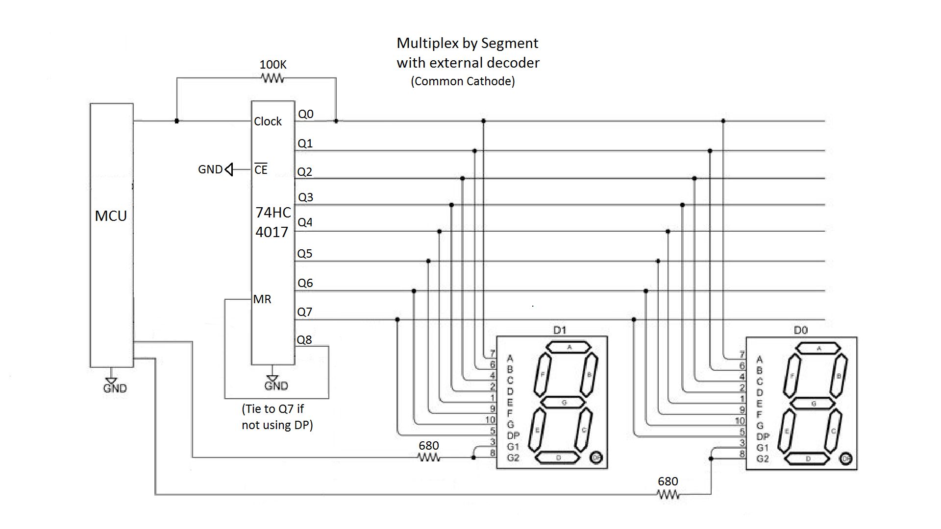
If you multiplex by segment instead of by digit, you can eliminate the segment line resistors, and just have one resistor per digit on its CC or CA pin.
Each segment would be turned on 1/7 of the time, with a maximum current load equal to three segments worth for a three-digit display.
If in addition you are using a constant cathode display, you could use a 74HC4017 to reduce the number of MCU pins needed. The HC4017 switches automatically to the next segment when clocked.
Interesting!... but how does the Arduino know which segment the HC4017 is selecting? Is a pulldown necessary on the Arduino pin connected to the clock, to prevent the clock input picking up false pulses when the Arduino pin is floating? Does the 100K shown do that somehow by acting as a pull-up?
If the Arduino looses track of how many pulses have been sent, for example because the user presses the Arduino reset or uploads code, is there any way for it to sync up with the HC4017 to know which segment needs to be lit currently?
Read the code. Or imagine it.
That 100K resistor is used to find the state of the '4017 by repeatedly clocking, then changing the pin to input mode and seeing if it's been clocked around to zero.
Clever enough.
This is in setup(), I'd be tempted to write a check and fix function to use every pass:
     //Clock the 4017 until the segment A output goes HIGH

  while (TEMP == LOW) {
    pinMode(CLOCK4017pin,INPUT);           //change port to INPUT (floating)
    TEMP = digitalRead(CLOCK4017pin);      //read state of Q0 (and Clock)
    digitalWrite(CLOCK4017pin,HIGH);       //must do this before changing back to output
    pinMode(CLOCK4017pin,OUTPUT);          //switching back to OUTPUT
                                           //     clocks the 4017 if Q0 was LOW
                                           //once Q0 reads HIGH, we're done - segment A ON
  }
a7
Ah yes!
This circuit could additionally drive up to 4 status LEDs using the Q8 & Q9 outputs of the HC4017.
It's all here:
https://github.com/gbhug5a/7-Segment-Displays-Multiplex-by-Segment
You could also connect another GPIO pin to the HC4017's reset pin. But the resistor lets you avoid that if pins are scarce.
I believe the seven segment library supports this through the "resistors on segments" boolean setting. But I don't think it supports the 4017.