Is there some chip that i can use for power delivery? Currently using a 12v 1A power supply and then a step down converter for the LED power
You can use the 12V for the LEDs, you just need to use 300 ohm currenting limiting resistors.
Then for the ESP you just need as 12V to 5V buck for the ESP Vin input.
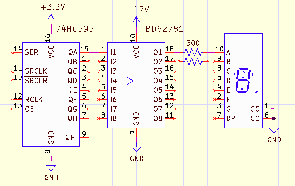
Dont i need 5V for the 74HC595 to work? And thanks for the image was about to draw one my self
The ESP has 3.3V I/O so you need to use 3.3V with the HC version
If you use a 74HCT595 then you can power it with 5V and use 3.3V signal levels.
SIx of one half dozen of the other as they say
Okay thanks,
I hope the new parts arive soon so i can start.
There was another person on the forum that was using 12 inch 7 seg displays that he found on Ebay. He used a similar circuit.
Do you have a link to that post? That would be usefull
I'm looking, it was maybe 2 years ago.
This is it but your way with the 595 is a bettor approach since nothing is multiplexed
Yeah found that one too,
But dont have that much I/O xD
Do you know any good learning material (Youtube/websites) to learn what I didn't understand and did wrong here? I won't be able to take Electrical Engineering 1 until the semester after next
Stay away from Youtube videos unless they are sponsored by a large IC manufacturer like Texas Inst, STMicro, Analog Devices, etc. The ones done by Tom , Dick and Harry seem to be mostly nonsense.
This website is good for learning the basics, they also have some videos.
https://www.allaboutcircuits.com/textbook/
Also if you go to the manufacturer's website of the ICs you are using, say TI(Texas Inst) they will usually have some application notes related to the part and information in general.
18 appnotes on the 595, see the one "Understanding and Interpreting Standard-Logic Data Sheets"
Okay then no YouTube, the website looks like a lot. So that will keep me busy for a while. Thank you
You don't need to read everything.
Mainly you will learn buy trial and error and asking others.
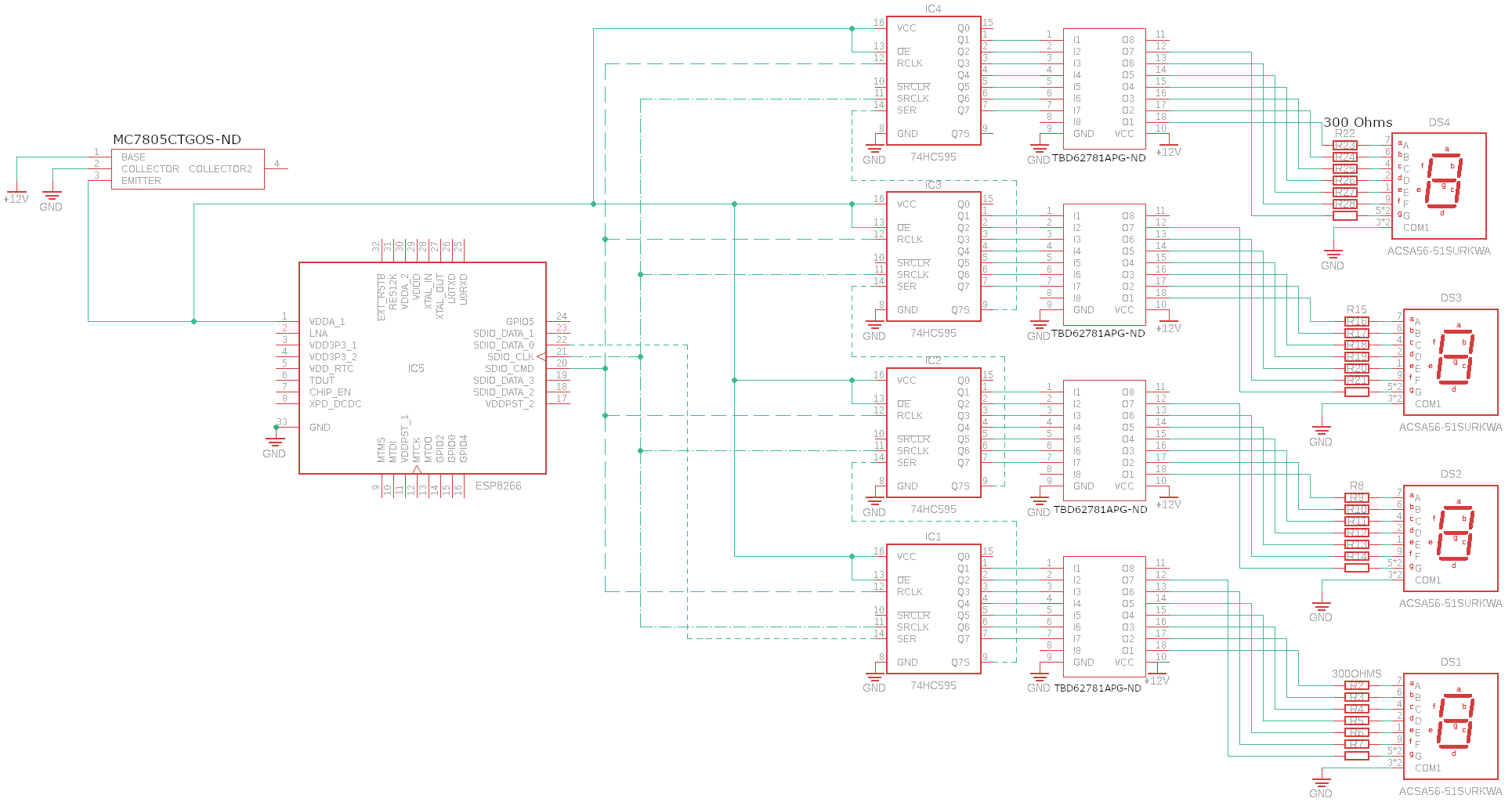
I think you have the wrong part number for the displays. The ACSA56-51SURKWA is not large, has Vf of 1.95V, and is common anode.
Yes, I forgot to mention here that I still have to change that
I still have to create the correct display in fusion
Thanks for the help my clock works now.
1 Like
This topic was automatically closed 180 days after the last reply. New replies are no longer allowed.