I am building an arcade game that needs to display time remaining (2 digits); score (3 digits); and high score (3 digits). I plan on using Sev.Seg library the programming for which I understand pretty well how to split one 8-digit number into three distinct numbers. However, I am struggling with the wiring schematic because I need to use a 7.2V power supply to illuminate a total of 8 individual LED seven-segment displays. The schematic that I have in mind looks like this:
Here is some information you may need to know:
Arduino Mega 2560 R3 is the microprocessor
Sev.Seg will be the library I plan to use for displaying numbers
7 segment displays (which I will refer to as "digits" going forward) are 7.2 volts, 20 mAmp, common cathode
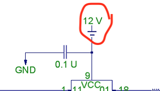
External power supply is 5V/12V/24V switching power supply. I am pulling off the 12V leg and using a buck converter regulator to step down the voltage to 7.2V
220-ohm resistors will be used in series for each anode pin of each digit
Tip120 NPN transistors will be used to isolate the Arduino while powering the digits on the anode side
Tip120 NPN transistors will be used so Arduino digital outputs can (de)multiplex each of the digits via the cathode side (ground pin)
The Arduino sketch will update the time remaining, score, and high score continuously. It will turn on one digit, update that value, and then shut it off. It will then do the same for the remaining digits so fast that it will appear all 8 digits are on at the same time.
I acknowledge that shift register(s) can be used to minimize digital outputs but I need to better understand the circuits first
Are there any concerns about this wiring schematic? If so can you make suggestions?
Yes I can't see remotely how this would work. It is beyond a single suggestion it is simply just wrong.
No base resistors on any of the transistors, lots of displays being powered through a single resistor. Switching voltages wrong, no obvious way that they are multiplexing. No sensible power supplies, or decoupling.
Can we break this down into bite-size pieces then?
Power Supply - I am using a separate power supply and then stepping down the voltage to 7.2V using a buck converter regulator. The 7.2 Volts are needed to power the digits. I also have 5V available if that is needed in this circuit.
Single Resistor on multiple displays - Yes the same pins are wired in parallel for each digit however since only one digit at a time will be on at a time (multiplexing), can't they share a resistor?
Multiplexing - the circuit for each digit would be "open" until the Arduino closes a digital switch so it can update that one digit and then open that circuit back up. The Arduino would then update all remaining digits one at a time and then repeat. This would be accomplished through the common cathode pin on each digit. I copied this idea from another forum thread but it was set up on digits that operate on 5 volts. Thoughts?
Base Resistors - I updated the image so it now shows the missing base resistors to each of the transistors.
Decoupling - Do I need to add a capacitor(s) somewhere? If so, then where?
Use a TBD62783A IC to drive the segments with a 12V supply and a 240 ohms resistor for each segment.
Then use a TBD62084 to drive the cathodes.
Otherwise you will need a bunch of transistors.
Thank you... this circuit diagram helps me a lot. One question so far... how does the voltage at each segment get regulated to 7.2V? Is that being done by the 240-ohm resistor? If so then I could get rid of my buck converter regulator.
If so then I could get rid of my buck converter regulator.
They put 4 LEDs in series for each segment. So if the nominal forward voltage of each LED is 1.8V, then 1.8V x 4 = 7.2V. So just treat it as a single 7.2V LED.
Resistor value = (12V-7.2V)/20mA = 240 ohms.
Do not use a ground symbol for the power input, it is not what the rest of the world does and it is most disturbing.
Next why feed the TBD62783A with12 Volts? I thought your 7 segment displays needed 7.2V and with the circuit you have you will get 12V outputs from this chip. If you want 7.2V out you must feed it with 7.2V input not 12V.
You can't use the 240R resistors to cut down the voltage, because as I said before the voltage drop will depend on how many segments will be on. So you need to supply the right voltage. Also you didn't post a link to these displays so we can't tell if they have any internal current limit. So forget the 240R resistors and feed the displays with what they are asking for.
Also check the data sheet for these two chips to see if you will be exceeding the maximum power dissipation for the chip.
The way to draw all the interconnections and make them look neat is to use a bus on the schematic. This is a thicker line that carry all the signals and peel off the one you want to use for the chip.
This is an example of how to draw a bus for a common anode seven segment display:-
In looking at the spec sheets, the max voltage to any of these is 5V. According to @Grumpy_Mike i need to use 7.2 volts. Since i am using CC, can you recommend decoders that will handle this load? Thanks.
The end of the model number is slightly different but i believe that to be the type of mounting pins. I'm looking to do this on a project board so the ...APG model looks correct to me. Thoughts?
Check again. I think that is the absolute rating, not the working rating. An absolute rating is the point where damage starts to happen. At the absolute rating it will not always work.
Well you still have the resistors in the driver.
Do you know there are two ways of driving the multiplexing, and depending on which way you choose could affect some of the circuit?
Maybe I should have started this thread like this. What's the best way to multiplex a total of 8 digits of 7 segment display (7.2 volts, cathode 20 mA)