Salve a tutti io ho problemi a far funzionare 7 vl6180x con l'arduino mega 2560....il settimo è come se non si avviasse.....qualcuno ha idee su come farli andare??il programma è quello X triple_vl di adafruit ma con l'aggiunta di adeguati PIN indirizzi eccetera per farne andare 6.....
Non conosco l'esempio in questione, ma immagino che mettendo tutti questi dispositivi in parallelo, l'aumento della capacità parassita che ne consegue diventi non trascurabile.
Potresti provare a diminuire il valore delle resistenze di pull-up, se è una cosa facilmente fattibile e/o a diminuire il clock del bus i2c.
Dai un'occhiata anche a questa application note del produttore.
Non ho resistenze di pull down esterne all'arduino....in più oltre a 6 vl6180x ho anche un apds 9960.... Il punto è che nel programma proprio si ferma sul vl.begin per avviare il sensore....
Si ferma perché il codice è scritto in modo tale che se il sensore non risponde entra in un while da cui non esce più.
  // initing LOX1
  if (!lox1.begin()) {
    Serial.println(F("Failed to boot first VL6180X"));
    while (1);
  }
Prova ad abbassare la velocità del clock:
void setup() {
  Wire.begin();
  Wire.setClock(50000); // Prova a 50 kHz o anche meno se necessario
  //  ...
}
Il bus I2C vuole obbligatoriamente delle resistenze di pull-up (NON pull-down), altrimenti non funziona, quindi, se funziona, quasi sicuramente, ciascuna di quelle breakout board che tu probabilmente stai usando (non credo che usi i sensori così come escono prodotti dalla fabbrica ![]() ) , ha a bordo le sue resistenze di pull-up, il che significa che ...
) , ha a bordo le sue resistenze di pull-up, il che significa che ...
... tu stai facendo un bel parallelo di resistenze fino a creare quasi un corto circuito.
Che moduli stai usando? Metti il LINK a tutti i moduli che stai usando.
Guglielmo
P.S.: NON solo, ma Arduino MEGA è una scheda particolare ... ha già a bordo, anche lei, delle resistenze di pull-up (verso i 5V) che si sommano al parallelo di altre resistenze di pull-up presenti sulle varie breakout board ![]()
Credo sia già a 50khz
Non credo che sia questo il caso, di solito le resistenze onboard sono da 4.7K
Lui ne usa 7 più quelle del mega che sono da 10K, quindi il parallelo fa circa 630 ohm.
Ipotizzando 5V per il livello HIGH, sono 8mA di corrente.

... che non mi sembra un valore accettabile sul bus I2C ... troppo basso.
Dovrebbe dissaldare le varie resistenze sul bus I2C delle varie breakout board che sta usando e, al limite, lasciarle solo su un paio di schedine ... ![]()
Guglielmo
Se avessi guardato schema di quelle schedine, ti saresti accorto che, ciascuna, ha le resistenze di pull-up a bordo ... ![]()
Continuo a pensare che il valore che si ottiene mettendole tutte in parallelo è troppo basso per il bus I2C della MEGA ...
Questo documento spiega come si calcola il valore:
I2C Bus Pullup Resistor Calculation.pdf (157.3 KB)
Guglielmo
Approfondo il problema che non ho spiegato bene prima.....io ho fatto il programma con questa base...
#include <Adafruit_VL6180X.h>

// address we will assign if dual sensor is present
#define LOX1_ADDRESS 0x30
#define LOX2_ADDRESS 0x31
#define LOX3_ADDRESS 0x32

// set the pins to shutdown
#define SHT_LOX1 7
#define SHT_LOX2 6
#define SHT_LOX3 5

// Optional define GPIO pins to check to see if complete
#define GPIO_LOX1 4
#define GPIO_LOX2 3
#define GPIO_LOX3 2

#define TIMING_PIN 13

// objects for the VL6180X
Adafruit_VL6180X lox1 = Adafruit_VL6180X();
Adafruit_VL6180X lox2 = Adafruit_VL6180X();
Adafruit_VL6180X lox3 = Adafruit_VL6180X();

// Setup mode for doing reads
typedef enum {RUN_MODE_DEFAULT, RUN_MODE_TIMED, RUN_MODE_ASYNC, RUN_MODE_GPIO, RUN_MODE_CONT} runmode_t;

runmode_t run_mode = RUN_MODE_DEFAULT;
uint8_t show_command_list = 1;

//==========================================================================
// Define some globals used in the continuous range mode
// Note: going to start table drive this part, may back up and do the rest later
Adafruit_VL6180X *sensors[] = {&lox1, &lox2, &lox3};
const uint8_t COUNT_SENSORS = sizeof(sensors) / sizeof(sensors[0]);
const int sensor_gpios[COUNT_SENSORS] = {GPIO_LOX1, GPIO_LOX2, GPIO_LOX3}; // if any are < 0 will poll instead

uint8_t         sensor_ranges[COUNT_SENSORS];
uint8_t         sensor_status[COUNT_SENSORS];
// Could do with uint8_t for 8 sensors, but just in case...
const uint16_t  ALL_SENSORS_PENDING = ((1 << COUNT_SENSORS) - 1);
uint16_t        sensors_pending = ALL_SENSORS_PENDING;
uint32_t        sensor_last_cycle_time;


/*
    Reset all sensors by setting all of their XSHUT pins low for delay(10), then set all XSHUT high to bring out of reset
    Keep sensor #1 awake by keeping XSHUT pin high
    Put all other sensors into shutdown by pulling XSHUT pins low
    Initialize sensor #1 with lox.begin(new_i2c_address) Pick any number but 0x29 and it must be under 0x7F. Going with 0x30 to 0x3F is probably OK.
    Keep sensor #1 awake, and now bring sensor #2 out of reset by setting its XSHUT pin high.
    Initialize sensor #2 with lox.begin(new_i2c_address) Pick any number but 0x29 and whatever you set the first sensor to
*/
void setID() {
  // all reset
  digitalWrite(SHT_LOX1, LOW);
  digitalWrite(SHT_LOX2, LOW);
  digitalWrite(SHT_LOX3, LOW);
  delay(10);

  // all unreset
  digitalWrite(SHT_LOX1, HIGH);
  digitalWrite(SHT_LOX2, HIGH);
  digitalWrite(SHT_LOX3, HIGH);
  delay(10);

  // activating LOX1 and reseting LOX2
  digitalWrite(SHT_LOX1, HIGH);
  digitalWrite(SHT_LOX2, LOW);
  digitalWrite(SHT_LOX3, LOW);

  // initing LOX1
  if (!lox1.begin()) {
    Serial.println(F("Failed to boot first VL6180X"));
    while (1);
  }
  lox1.setAddress(LOX1_ADDRESS);
  delay(10);

  // activating LOX2
  digitalWrite(SHT_LOX2, HIGH);
  delay(10);

  //initing LOX2
  if (!lox2.begin()) {
    Serial.println(F("Failed to boot second VL6180X"));
    while (1);
  }
  lox2.setAddress(LOX2_ADDRESS);

  // activating LOX3
  digitalWrite(SHT_LOX3, HIGH);
  delay(10);

  //initing LOX3
  if (!lox3.begin()) {
    Serial.println(F("Failed to boot third VL6180X"));
    while (1);
  }
  lox3.setAddress(LOX3_ADDRESS);
}

void readSensor(Adafruit_VL6180X &vl) {
  Serial.print(" Addr: ");
  Serial.print(vl.getAddress(), HEX);

  float lux = vl.readLux(VL6180X_ALS_GAIN_5);
  Serial.print(" Lux: "); Serial.print(lux);
  uint8_t range = vl.readRange();
  uint8_t status = vl.readRangeStatus();

  if (status == VL6180X_ERROR_NONE) {
    Serial.print(" Range: "); Serial.print(range);
  }

  // Some error occurred, print it out!

  if  ((status >= VL6180X_ERROR_SYSERR_1) && (status <= VL6180X_ERROR_SYSERR_5)) {
    Serial.print("(System error)");
  }
  else if (status == VL6180X_ERROR_ECEFAIL) {
    Serial.print("(ECE failure)");
  }
  else if (status == VL6180X_ERROR_NOCONVERGE) {
    Serial.print("(No convergence)");
  }
  else if (status == VL6180X_ERROR_RANGEIGNORE) {
    Serial.print("(Ignoring range)");
  }
  else if (status == VL6180X_ERROR_SNR) {
    Serial.print("Signal/Noise error");
  }
  else if (status == VL6180X_ERROR_RAWUFLOW) {
    Serial.print("Raw reading underflow");
  }
  else if (status == VL6180X_ERROR_RAWOFLOW) {
    Serial.print("Raw reading overflow");
  }
  else if (status == VL6180X_ERROR_RANGEUFLOW) {
    Serial.print("Range reading underflow");
  }
  else if (status == VL6180X_ERROR_RANGEOFLOW) {
    Serial.print("Range reading overflow");
  }
}

void read_sensors() {
  readSensor(lox1);
  readSensor(lox2);
  readSensor(lox3);
  Serial.println();
}

void timed_read_sensors() {
  digitalWrite(TIMING_PIN, HIGH);
  uint32_t start_time = millis();
  uint8_t range_lox1 = lox1.readRange();
  uint8_t status_lox1 = lox1.readRangeStatus();
  uint8_t range_lox2 = lox2.readRange();
  uint8_t status_lox2 = lox2.readRangeStatus();
  uint8_t range_lox3 = lox3.readRange();
  uint8_t status_lox3 = lox3.readRangeStatus();
  uint32_t delta_time = millis() - start_time;
  digitalWrite(TIMING_PIN, LOW);
  Serial.print(delta_time, DEC);
  Serial.print(" : ");
  if (status_lox1 == VL6180X_ERROR_NONE) Serial.print(range_lox1, DEC);
  else Serial.print("###");
  Serial.print(" : ");
  if (status_lox2 == VL6180X_ERROR_NONE) Serial.print(range_lox2, DEC);
  else Serial.print("###");
  Serial.print(" : ");
  if (status_lox3 == VL6180X_ERROR_NONE) Serial.print(range_lox3, DEC);
  else Serial.print("###");

  Serial.println();
}

void timed_async_read_sensors() {
  digitalWrite(TIMING_PIN, HIGH);
  uint32_t start_time = millis();

  // lets start up all three
  lox1.startRange();
  lox2.startRange();
  lox3.startRange();

  // wait for each of them to complete
  lox1.waitRangeComplete();
  lox2.waitRangeComplete();
  lox3.waitRangeComplete();

  uint8_t range_lox1 = lox1.readRangeResult();
  uint8_t status_lox1 = lox1.readRangeStatus();
  uint8_t range_lox2 = lox2.readRangeResult();
  uint8_t status_lox2 = lox2.readRangeStatus();
  uint8_t range_lox3 = lox3.readRangeResult();
  uint8_t status_lox3 = lox3.readRangeStatus();
  uint32_t delta_time = millis() - start_time;
  digitalWrite(TIMING_PIN, LOW);
  Serial.print(delta_time, DEC);
  Serial.print(" : ");
  if (status_lox1 == VL6180X_ERROR_NONE) Serial.print(range_lox1, DEC);
  else Serial.print("###");
  Serial.print(" : ");
  if (status_lox2 == VL6180X_ERROR_NONE) Serial.print(range_lox2, DEC);
  else Serial.print("###");
  Serial.print(" : ");
  if (status_lox3 == VL6180X_ERROR_NONE) Serial.print(range_lox3, DEC);
  else Serial.print("###");

  Serial.println();

}

void timed_async_read_gpio() {
#ifdef GPIO_LOX1
  uint8_t range_lox1 = 0;
  uint8_t status_lox1 = VL6180X_ERROR_NONE;
  uint8_t range_lox2 = 0;
  uint8_t status_lox2 = VL6180X_ERROR_NONE;
  uint8_t range_lox3 = 0;
  uint8_t status_lox3 = VL6180X_ERROR_NONE;


  digitalWrite(TIMING_PIN, HIGH);
  uint8_t pending_sensors = 0x7;
  uint32_t start_time = millis();

  // lets start up all three
  lox1.startRange();
  lox2.startRange();
  lox3.startRange();

  while (pending_sensors && ((millis() - start_time) < 1000)) {
    if ((pending_sensors & 0x1) && !digitalRead(GPIO_LOX1)) {
      range_lox1 = lox1.readRangeResult();
      status_lox1 = lox1.readRangeStatus();
      pending_sensors ^= 0x1;
    }
    if ((pending_sensors & 0x2) && !digitalRead(GPIO_LOX2)) {
      range_lox2 = lox2.readRangeResult();
      status_lox2 = lox2.readRangeStatus();
      pending_sensors ^= 0x2;
    }
    if ((pending_sensors & 0x4) && !digitalRead(GPIO_LOX3)) {
      range_lox3 = lox3.readRangeResult();
      status_lox3 = lox3.readRangeStatus();
      pending_sensors ^= 0x4;
    }
  }
  uint32_t delta_time = millis() - start_time;
  digitalWrite(TIMING_PIN, LOW);
  Serial.print(delta_time, DEC);
  Serial.print("(");
  Serial.print(pending_sensors, DEC);
  Serial.print(") : ");
  if (status_lox1 == VL6180X_ERROR_NONE) Serial.print(range_lox1, DEC);
  else Serial.print("###");
  Serial.print(" : ");
  if (status_lox2 == VL6180X_ERROR_NONE) Serial.print(range_lox2, DEC);
  else Serial.print("###");
  Serial.print(" : ");
  if (status_lox3 == VL6180X_ERROR_NONE) Serial.print(range_lox3, DEC);
  else Serial.print("###");

  Serial.println();
#endif
}

//===============================================================
// Continuous range test code
//===============================================================
void start_continuous_range() {
  Serial.println("start Continuous range mode");
  for (uint8_t i = 0; i < COUNT_SENSORS; i++) {
    sensors[i]->startRangeContinuous();
  }
  sensors_pending = ALL_SENSORS_PENDING;
  sensor_last_cycle_time = millis();
}

void stop_continuous_range() {
  Serial.println("Stop Continuous range mode");
  for (uint8_t i = 0; i < COUNT_SENSORS; i++) {
    sensors[i]->stopRangeContinuous();
  }
  delay(100); // give time for it to complete.
}


void Process_continuous_range() {

  uint16_t mask = 1;
  for (uint8_t i = 0; i < COUNT_SENSORS; i++) {
    bool range_complete = false;
    if (sensors_pending & mask) {
      if (sensor_gpios[i] >= 0)
        range_complete = !digitalRead(sensor_gpios[i]);
      else
        range_complete = sensors[i]->isRangeComplete();
      if (range_complete) {
        sensor_ranges[i] = sensors[i]->readRangeResult();
        sensor_status[i] = sensors[i]->readRangeStatus();
        sensors_pending ^= mask;
      }
    }
    mask <<= 1; // setup to test next one
  }
  // See if we have all of our sensors read OK
  uint32_t delta_time = millis() - sensor_last_cycle_time;
  if (!sensors_pending || (delta_time > 1000)) {
    Serial.print(delta_time, DEC);
    Serial.print("(");
    Serial.print(sensors_pending, HEX);
    Serial.print(")");
    mask = 1;
    for (uint8_t i = 0; i < COUNT_SENSORS; i++) {
      Serial.print(" : ");
      if (sensors_pending & mask) Serial.print("TTT");  // show timeout in this one
      else if (sensor_status[i] == VL6180X_ERROR_NONE) Serial.print(sensor_ranges[i], DEC);
      else {
        Serial.print("#");
        Serial.print(sensor_status[i], DEC);
      }
    }
    // setup for next pass
    Serial.println();
    sensor_last_cycle_time = millis();
    sensors_pending = ALL_SENSORS_PENDING;
  }
}

//===============================================================
// Setup
//===============================================================
void setup() {
  Serial.begin(115200);

  // wait until serial port opens for native USB devices
  while (! Serial) {
    delay(1);
  }

  pinMode(SHT_LOX1, OUTPUT);
  pinMode(SHT_LOX2, OUTPUT);
  pinMode(SHT_LOX3, OUTPUT);

  // Enable timing pin so easy to see when pass starts and ends
  pinMode(TIMING_PIN, OUTPUT);

#ifdef GPIO_LOX1
  // If we defined GPIO pins, enable them as PULL UP
  pinMode(GPIO_LOX1, INPUT_PULLUP);
  pinMode(GPIO_LOX2, INPUT_PULLUP);
  pinMode(GPIO_LOX3, INPUT_PULLUP);
#endif

  Serial.println("Shutdown pins inited...");

  digitalWrite(SHT_LOX1, LOW);
  digitalWrite(SHT_LOX2, LOW);
  digitalWrite(SHT_LOX3, LOW);
  digitalWrite(TIMING_PIN, LOW);
  Serial.println("All in reset mode...(pins are low)");


  Serial.println("Starting...");
  setID();

}

//===============================================================
// Loop
//===============================================================
void loop() {
  if (Serial.available()) {
    uint8_t ch = Serial.read();
    while (Serial.read() != -1) ; // remove the rest
    runmode_t prev_run_mode = run_mode;
    // See what the user typed in
    switch (ch) {
      case 'd':
      case 'D':
        run_mode = RUN_MODE_DEFAULT;
        break;
      case 't':
      case 'T':
        run_mode = RUN_MODE_TIMED;
        break;
      case 'a':
      case 'A':
        run_mode = RUN_MODE_ASYNC;
        break;
#ifdef GPIO_LOX1
      case 'g':
      case 'G':
        run_mode = RUN_MODE_GPIO;
        break;
#endif
      case 'c':
      case 'C':
        run_mode = RUN_MODE_CONT;
        break;

      default:
        show_command_list = 1;
        run_mode = RUN_MODE_DEFAULT;
    }
    if (run_mode != prev_run_mode) {
      // if previous mode was continuous mode, shut it down
      if (prev_run_mode == RUN_MODE_CONT) stop_continuous_range();
      if (run_mode == RUN_MODE_CONT) start_continuous_range();
    }
  }
  if (show_command_list) {
    Serial.println("\nSet run mode by entering one of the following letters");
    Serial.println("    D - Default mode");
    Serial.println("    T - Timed mode - Reads done one after another");
    Serial.println("    A - Asynchronous mode - Try starting all three at once");
#ifdef GPIO_LOX1
    Serial.println("    G - Asynchronous mode - Like above use GPIO pins");
#endif
    Serial.println("    C - Continuous mode - Try starting all three at once");
    show_command_list = 0;
  }
  switch (run_mode) {
    case RUN_MODE_DEFAULT:
      read_sensors();
      break;
    case RUN_MODE_TIMED:
      timed_read_sensors();
      break;
    case RUN_MODE_ASYNC
      timed_async_read_sensors();
      break;
    case RUN_MODE_GPIO:
      timed_async_read_gpio();
      break;
    case RUN_MODE_CONT:
      Process_continuous_range();
  }
  delay(100);
}
qui il programma potrebbe andare con 8 sensori ..... Ma qui quando metto il sensore 7 prima di assegnare l'indirizzo si ferma sul vl.begin.....
È banale ma non si sa mai...
Hai provato a scambiare di posto i vari sensori per vedere se si ferma sempre al settimo?
Certo provato a scambiare fisicamente sia via address...se cambio address e metto il settimo sensore come primo allora il primo che viene scambiato al posto del settimo non funziona
... che NON mi sembra vada bene come valore (dal datasheet del ATmega2560):

... a VCC 5V il minimo è 1533Ω ![]()
Guglielmo
1 Like
... cosa non ti è chiaro nel fatto che, molto probabilmente, stai sovraccaricando, con tutte quelle pull-up, il bus I2C ???
Guglielmo
Quindi o lascio stare oppure devo dissaldare alcune pullup dei sensori...?
... prima di tutto devi individuare QUALI sono le pull-up, visto che su quelle schedine ci sono varie resistenze, e poi, almeno sulla metà, io le eliminerei (marcati quali non avranno più le pull-up, perché, se un giorno le vuoi usare da sole, ce le devi aggiungere)
Guglielmo
P.S.: T'ho chiesto di mettere il LINK al prodotto, non una foto, così vediamo di trovare gli schemi!!!!
... aggiungo che, dato che il sensore lavora a 2.8V, su quelle schedine, oltre al regolatore di tensione per alimentalo, ci sono sicuramente dei level shifter, per adattare il bus I2C del sensore con i livelli del bus I2C esterno (a 5V), quindi occorre individuare quali sono le resistente che sono lato 5V e non lato 2.8V.
Ad esempio, un modulo simile fatto da Pololu ha il seguente schema:
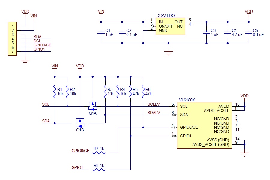
e si vedono bene delle pull-up da 10K da entrambi i lati dei MOSFET adattatori di livello ![]()
Guglielmo
5pcs VL6180 VL6180X Range Finder Optical Ranging Time-of-Flight Distance Senor : Amazon.it: Commercio, Industria e Scienza questo è il link ....li ho comprati su Amazon ma non ho la più pallida idea se hanno uno schema elettrico....
Comunque attualmente ho un apds 9960 6 vl6180x e 2 bno055.... effettivamente potrebbe essere quello il problema...anche se però aggiungo un'altro apds9960 riesce a farlo funzionare....